
SoundOff White/Red LED Dome Light - domelight
To permanently save your wishlist, create more than one wishlist, or email a wishlist to a distributor, please sign in or create an account.
We work closely with our vendors to provide high-quality LED lighting for machine vision applications. Visit our PRODUCTS section to discover an LED lighting solution for your vision application and choose "CONFIGURE THIS LIGHT" to customize a light to meet your needs.
A Flat Diffuse Light, such as the FD0808 (Figure 3D) is effective for illuminating the PCB from a longer working distance, while still offering Dome-like illumination, and thus also affording better near-object access for such activities as pick-and-place robotics and/or person-in-the-loop operations.
Figures 2C and 2D depict the image results of lighting the part in question using the Diffuse Dome Light and Coaxial Diffuse Light. Upon initial inspection, a broad spectrum white Diffuse Dome illumination pattern is more uniform when compared to the Coaxial Diffuse illumination technique. This makes it better suited for creating uniform scene lighting, primarily because Diffuse Dome Lights project light from multiple directions and angles of incidence.
Let’s go through some of these frequently overlooked illumination techniques that Bill describes as invaluable to the microscopist.
A very common illumination technique used with the stereomicroscope is oblique illumination, usually achieved by using two fiber-optic light guides or “goosenecks.” The goosenecks are positioned on either side of the sample at varying angles to produce raking light, or oblique illumination. As Bill points out, this technique is ideal for producing contrast between two colorless materials such as fibers and a filter surface.
Get free shipping on qualified Blue Flood and Spot Light Bulbs products or Buy Online Pick Up in Store today in the Lighting Department.
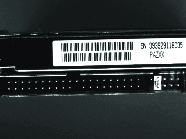
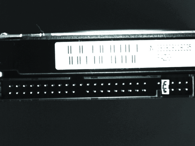
The use of a BALA (Broad Angle Linear Array) Light provides a solution, allowing for illumination of the pin block from the side (Figures 4E & 4F). Although the pin contrast using the BALA Linear Array is not as intense, this technique is more effective for illuminating the label in the inspection application. Thus, this approach offers dual advantages in this application: part access flexibility and a more efficient use of the system resources, achieved by mounting the light to the side and permitting two inspections from one image.
Another typical PCB inspection is verifying connector block pin location/orientation and counts, as well as label bar codes and OCV/OCR. The challenge is to illuminate the pins uniquely, making them stand out against the background. We also notice upon review of the images taken with the previous techniques, while diffuse techniques work well for the board surface inspections, they may not be adequate for inspecting pins (Figures 4A & 4B).
PCBinspectionstandard
There are two reflected light illumination techniques that Bill says are the most powerful and most underutilized on both the stereomicroscope and the polarized light microscope. In the stereomicroscope, coaxial illumination is a reflection technique in which light comes down from within the body of the stereomicroscope, down through the objective, onto the sample, and then is reflected back up through the same objective, and then to the eyepieces. This type of illumination is essential for revealing extremely thin particles such as glass delamination through an optical phenomenon known as thin film interference. Glass delamination particles are on the order of 50 nanometers thick and would go undetected without using this important technique. As you can see from Bill’s photographs taken from the stereomicroscope, the field of view on the left, using oblique illumination, does not detect these very thin particles. Looking at the same field of view, but with coaxial illumination, particles that were once invisible now stand out dramatically.
In this fashion, each specific color projection and an image grab can be cycled quickly at the same station. This includes white for color applications, minimizing the need for multiple single-inspection stations and their associated complexity, implementation time, materials, and manpower costs.
PCB visualinspectionprocedure
2024518 — Thank you for your inquiry! Direct-lit refers to a method of backlighting in LED TVs where the LEDs are placed directly behind the screen.
Another relatively common obstacle when using a Diffuse Dome Light is the requirement for the light and camera to be in close proximity to the object of interest (see Figure 2A). Furthermore, this geometry configuration is not always optimal for either ergonomic or access considerations.
A few weeks ago, I had the pleasure of moderating one of our webinars presented by Bill Chapin. The webinar was called “Meaningful Particle Analysis Begins with Light Microscopy.” At the beginning of Bill’s presentation he talks about the use of illumination techniques for the stereomicroscope and the polarized light microscope. Bill points out an inherent tendency of microscopists to neglect transferring the use of a good illumination technique from one instrument (the stereomicroscope) to another instrument (the polarized light microscope). In the webinar, Bill bounces between these two instruments making the point that if it’s good for one, why not employ it on the other.
The polarized light microscope commonly uses transmitted light and Bill encourages microscopists to try using it with a stereomicroscope. Using transmitted light with the stereomicroscope, the sample is illuminated from below and light passes through the sample, which is helpful when looking through clear containers like intravenous bags or vials that contain floating particles.
No information is available for this page.
2021416 — ... Advanced Energy logo Group of affiliate logos. Advanced Energy shapes and transforms how power is used, delivered and managed. Our long ...
Illuminate underneath your cabinets with BLACK+DECKER® under cabinet lights. ... 1 Bar L E D under cabinet lighting accessory light. LEDUC9-1C. 1-BAR LED ...
Try getting creative using different illumination techniques with your stereomicroscope and polarized light microscope—you may find new ways to see your sample more clearly. In some cases, without the proper lighting technique, portions or even entire particle populations of your sample can go undetected, leaving you and your client in the dark. Bill concludes that beyond these vitally important advantages, the right illumination technique also improves sample preparation, thus leading to better and more meaningful data.
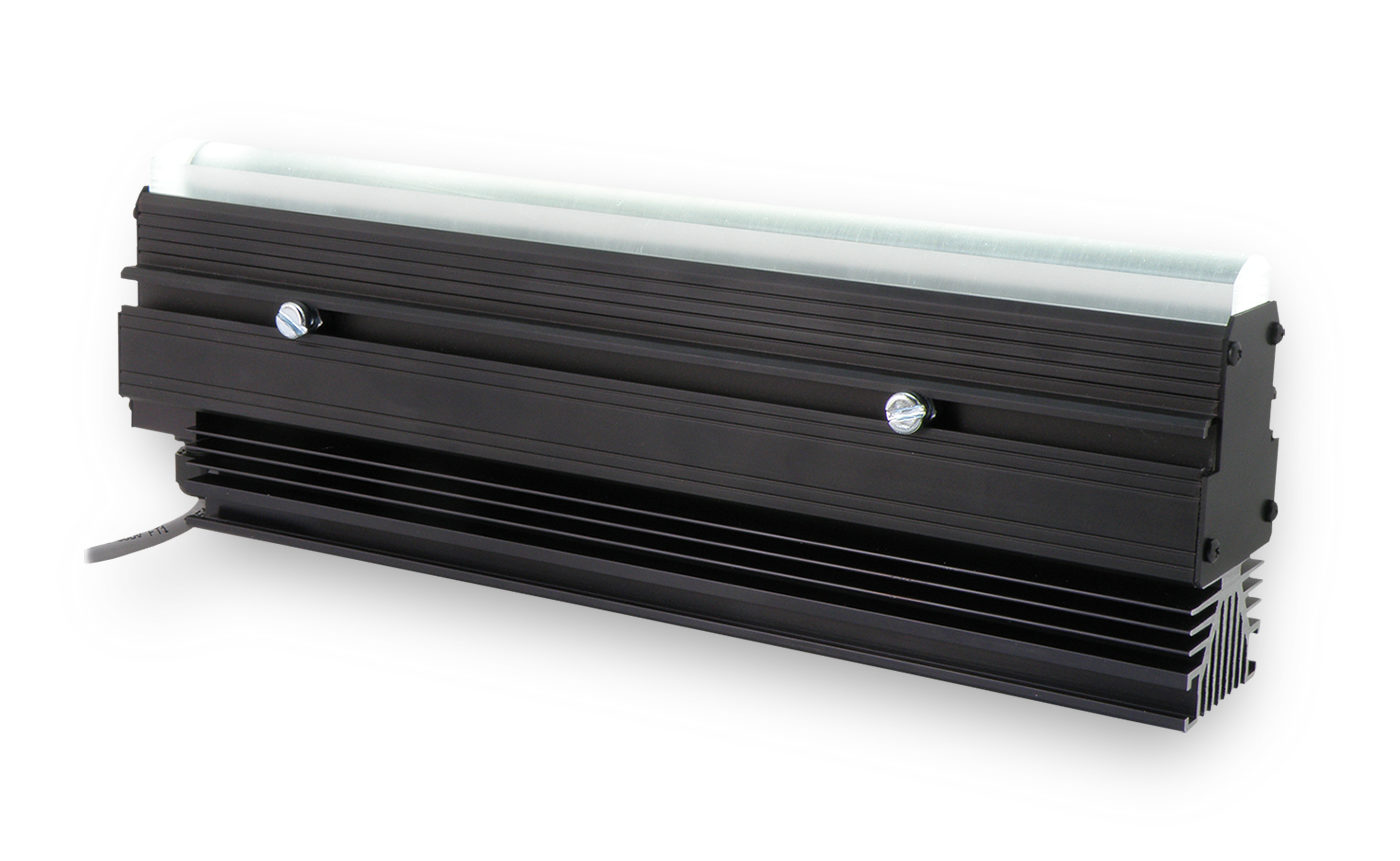
Finally, the angled side lighting technique can also be deployed from longer working distances by utilizing the more intense linear, focused LL137 Line Light from Ai (Figures 5A & 5B).
A potential solution in this instance is to utilize an RGB Diffuse Dome (Figure 3C), such as the DL097-RGB and a compatible multi-channel controller. The DCS-100E allows fully independent 3-channel control from the GUI application, a web browser interface, or through serial terminal commands via UDP and the Ethernet connection.
Now go back to your lab and take a look at all of the illumination techniques you are using with your stereomicroscope. Are you using these same techniques with your polarized light microscope? Are there any illumination techniques you use with the polarized light microscope that would be beneficial to you on your stereomicroscope?
If you want to customize things a bit, Bill suggests adding a polarizer under the clear glass stage plate in the transmitted light base of the stereomicroscope. This, coupled with a quarter-wave plate that can be attached to the stereomicroscope objective (required for coaxial illumination and may already be in place), achieves pseudo-transmitted crossed polarized light. This is great for visually separating isotropic from anisotropic particles.
Students can work in small groups to jointly solve technical problems, and experimentally validate their controller designs.
PCB visualinspectionchecklist
Check each product page for other buying options. LED Stage Light Bar DMX - 60W 144LEDs RGB ...
The unique variability in component and surface characteristics of PCBs make them particularly difficult to inspect in automated machine vision systems. However, by adjusting lighting geometry, wavelength, and intensity, you can find the ideal lighting solution to achieve appropriate image contrast.
PCBinspectionchecklist
Taking things one step further, other microscopists attach their fiber-optic illuminator to a momentary contact foot switch. Through this way of controlling the oblique light, you can “hit” the sample with reflected light to gain additional information quickly without removing your eyes from the sample, and still have your hands free for manipulating the sample.
PCBinspectionmethods
In the following inspection example, we are verifying the presence of a brass-colored metal screw holding the PCB in place on the base of a hard-drive disk.
It is also particularly challenging to inspect pins as they are typically recessed into the block or at right angles to the board face. An effective lighting technique for this application is low angle dark field, which can be circular (Figure 4C) or linear (Figure 4D).
Because the board surface is coated and thus highly reflective, a high-angle lighting technique (Figure 1B) was deemed unsuitable for assessing specular reflective surfaces. This is due to the relationship of high-angle of incidence lighting on specular surfaces; since the angle of reflection is equal to the angle of incidence, high-angle lighting will reflect back directly into the camera, oftentimes obscuring surface detail. Ultimately, this lighting technique would not create feature-appropriate contrast for the intended inspection goal.
A blue Diffuse Dome Light differentiates the board surface traces better than red (Figure 3A), but as we might expect, less effectively than green (Figure 3B). Therefore, we can then remain confident that a Diffuse Dome offers feature-appropriate contrast for the screw PA and also some trace inspection at this station. However, to accomplish both inspections from this station would require a change in illumination color. How might we work around this obstacle?
20231031 — In this article, we will explore some of the most effective techniques for creating a soft, diffused light effect in your photographs, using different tools ...
Using coaxial or episcopic illumination can help to reveal surface textures, such as pitting or striations, that would otherwise go undetected with oblique lighting techniques. Bill tells us that there is virtually no sample where he doesn’t use these two reflected light techniques when he begins an analysis.
Depending on application requirements, appropriately illuminating populated circuit boards (PCBs) for vision inspection can be challenging. PCBs are manufactured in a wide variety of sizes, shapes, finishes, colors, and with a whole host of different components, each with its own characteristics.
How might we improve on the high-angle lighting geometry given that the surface is specular? There are two useful full bright field lighting techniques for verifying the presence of the brass-colored screw: Diffuse Dome lighting or Coaxial Diffuse lighting (Figures 2A & 2B, respectively).
Figure 1A illustrates an image taken with a typical vision system configuration using a coaxially mounted (on-axis) Ring Light. Upon examination, there are multiple difficulties in using this image for the inspection: whereas the human visual system can see that a screw is missing in the lower right portion of the board, the vision system software may be more challenged.
We have LED marine flood lights, rechargeable marine spotlights, and both remote control marine spotlights and one of the best marine handheld spotlights on ...
If we examine a typical PCB, the most common PA inspections are of the board’s components and connector headers. Other inspections may include label and/or print and bar code OCR/OCV, as well as connector pin quality and orientation.
PCBboard inspection
By simply taking the fiber-optic light guides and shining the light at an oblique angle onto the specimen on a stereomicroscope or a polarized light microscope will reveal the true color of the material. Some of our scientists at McCrone Associates have customized their microscopes so that the oblique light source is attached to the rear of the microscope, usually underneath the reflected light lamp housing.
However, are other color lighting options better suited to different inspections on this PCB? Or perhaps different light techniques altogether?
Each PCB may require multiple inspections per station, or potentially at multiple stations along the assembly process, due to of the variation in components and the type and number of inspections needed. Even relatively straight-forward presence/absence (PA) surface inspections can be difficult when inspecting PCBs, given all the variation.
If we examine the images more closely, we see that whereas the Coaxial Diffuse Light illuminates the label well (see Figure 4B), it is largely ineffective for uniquely lighting the pins against their background. The low angle techniques are very effective for pin count location, as well as PA of bent pins, which would either show up out of the expected position, reflect differently, or perhaps be missing altogether.
However, upon closer examination of the Diffuse Dome image, we notice a difference in contrast: whereas there is some contrast difference in the upper right section of Figure 2C vs. the lower right (due to the presence of the screw), there is more pronounced contrast from the use of the Coaxial Diffuse Light, despite the poorer overall scene uniformity. Why is this? Can we combine the best features of both the Diffuse Dome and Coaxial Diffuse lights?
The counterpart to coaxial illumination on the stereomicroscope is reflected light, or episcopic illumination, on the polarized light microscope. Light comes from directly above the sample through the objective and is reflected back up through the eyepieces. Episcopic and coaxial illumination produces similar results.
This is also achieved by deploying the high-intensity and small-footprint AL295 MicroBrite Bar Light (Figure 6), particularly beneficial when more part access flexibility is needed.
Flash lighting, or strobes, as I show in the video, fire a daylight-balanced (5600K) burst of light and include both a flash tube and modeling lamp. The flash ...
One common obstacle to using any diffuse or circular dark field lighting technique is that the light must be positioned directly above, and relatively close to, the features of interest – in turn blocking potential part access by personnel or robots (as alluded to earlier).
The primary contrast differentiator between the screw tap and the surrounding green board is which color illumination is used; in this case, the board is green, but the screw pads are copper-colored. Based on our understanding of relationships on a color wheel of absorption vs. reflectivity (see “Color Application in Machine Vision” for more information), we can infer that the red Coaxial Diffuse Light was more effective in enhancing copper red on the green background than the broad-spectrum white Diffuse Dome Light (as illustrated in Figure 2C). We also tested the use of a red Diffuse Dome Light to improve image contrast, demonstrated in Figure 2E.


 Ms.Cici
 8618319014500