
Prime Freshwater - ai lights
The customizable options within the Ai Quad Controllers enable users to tailor their Photometric Stereo application to their unique inspection needs. Figures 6A & 6B demonstrate a series with four separate events, requiring four triggers from the camera to complete the sequence.
When implementing Photometric Stereo, it may be tempting to capture as many images as possible using as many light angles as possible. After all, increasing the number of images taken with different light angles results in additional data points for the software to produce a more robust image4. However, it is important to note that a light source placed too closely to the object’s surface during inspection can present a problem when trying to process a large number of images in one application. This is because when a large number of images with strong shadows are processed, an over-smoothing of the depth map4 and a lower-contrast image are a common result. Thus, it is important to consider the distance of the light source from the object being illuminated, as near-light photometric stereo often produces stronger shadows and an increased number of occlusions.
Photometric stereopdf
Figure 8A – Input images of a threaded metallic part inspected with a DF198 MicroBriteTM Diffuse Ring Light and DCS-400E Quad Controller
Photometric stereogithub
5. Lina, A., Boriero, P., & Ostrowski, K. (2019, June 1). Photometric stereo techniques analyze reflections to improve image contrast. Retrieved from https://www.laserfocusworld.com/lasers-sources/article/14035413/photometric-stereo-techniques-analyze-reflections-to-improve-image-contrast
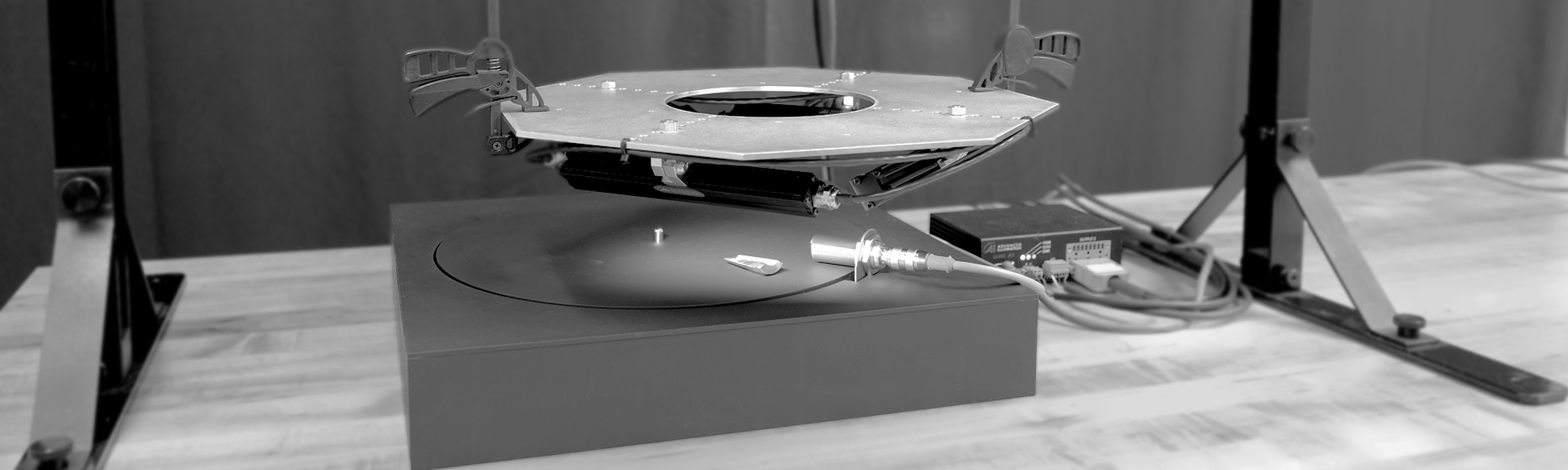
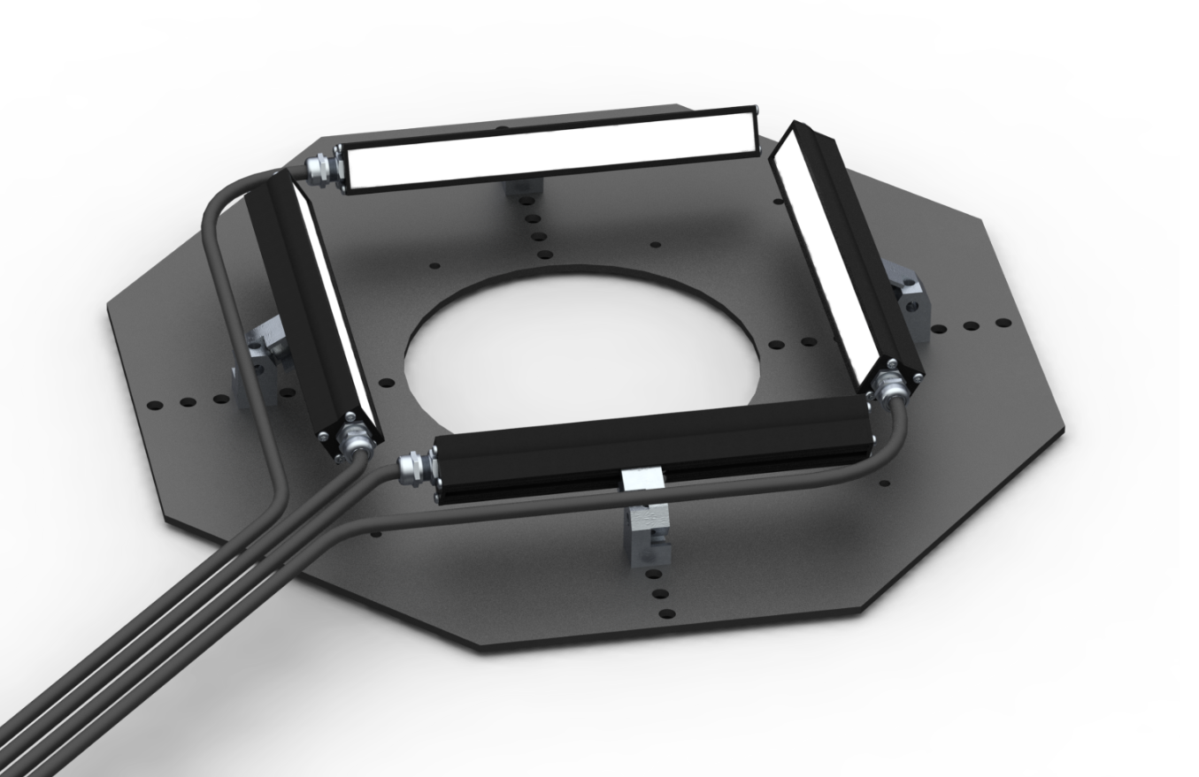
To acquire images from multiple illumination directions, one may use either a multi-segmented light, such as the DF198 MicroBriteTM Diffuse Ring Light Series (Figure 2) or a multi-light station (Figure 3). Each option provides the opportunity to illuminate from multiple source directions, or with multiple wavelengths, to achieve the necessary direction-dependent surface albedos. A versatile multi-channel lighting controller is the most effective solution to drive multi-segmented or a multi-light station and provide the necessary sequencing and hand-shaking capabilities.
However, there are provisions within the Photometric Software to facilitate the inspection of moving objects. While the objects themselves cannot always be physically adjusted to ensure consistent placement of surface data points, the images taken can be reoriented, or re-registered, within the software to compensate for the object’s movement. Additional, full-illumination images can be taken to establish the object’s displacement5 to further help for the tracing of the object’s changing positions throughout the inspection process.
The following threaded metallic part presents another challenge for standard vision light and camera configurations. The varying heights of the object’s threads create significant shadowing, making it very difficult to visually inspect for defects. The metallic surface also presents a challenge with unwanted specular reflections.
The multi-channel controllers feature a GUI with either Standard or Sequenced Mode. Standard Mode works like a traditional strobe controller, firing all channels with a fixed delay and pulse width. Figures 5A-5C demonstrate the software interfaces of both the DCS-400E and DCS-800E in Standard Mode.
We work closely with our vendors to provide high-quality LED lighting for machine vision applications. Visit our PRODUCTS section to discover an LED lighting solution for your vision application and choose "CONFIGURE THIS LIGHT" to customize a light to meet your needs.
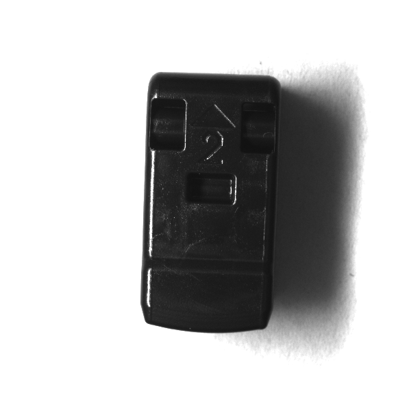
Pulsing either multiple lights or a single multi-segment light in a sequence around an object then produces shadows that can be processed with an image library Photometric Stereo registration algorithm. Combining the images together (seen earlier in the black plastic clip example in Figure 1) provides an enhanced inspection of the surface.
Part inspections applying Photometric Stereo benefit from the ability to “flatten” surfaces with 3D characteristics that can distort an image in common machine vision applications. We’ll examine two objects with different challenges to demonstrate the benefits of applying Photometric Stereo.
Using the Matrox Design Assistant and Imaging Library (MIL) to process the images, the final image appears flat – resulting in an easily identifiable printed lot code in Figure 7B.
Machine vision is commonly deployed in part inspections to gather feature-appropriate identifying information from an object’s surface and to increase the speed, accuracy and consistency of the inspection process. For many surfaces, simple defects such as scratches and dents are easily identifiable with a machine vision camera and a traditional lighting solution.
The figure shows directional light originating from a point source that covers a larger area the further away it is from the source. As the light travels it has a specific brightness and size at any given point. The inverse square law shows that when light travels twice the distance its area grows four times as large and the brightness decreases by four times. The rate a light grows in area and decreases in brightness is related to the distance it travels from another point squared.
Figure 7A – Input images of a vitamin bottle bottom inspected with a DF198 MicroBriteTM Diffuse Ring Light and DCS-400E Quad Controller
However, some objects have 3D aspects that make accurately identifying surface defects more difficult, such as embossing, textured or highly reflective surfaces, as well as those objects exhibiting little to no feature contrast or texture. A standard vision light and camera configuration, typically used in machine vision, only captures images from a single illumination/viewer perspective. Therefore, it may be ineffective in certain applications, as local surface shapes (including embossing or other 3D details) cannot, in general, be determined from an intensity value recorded at a single image point1. To achieve feature-appropriate surface contrast on these difficult object surfaces and ultimately gather a 3D perspective, Photometric Stereo may be applied to vary the direction of incident illumination between successive views, while holding the viewing direction constant.1
Photometric stereodataset
You can find this page online at: https://www.sciencebuddies.org/science-fair-projects/project-ideas/Elec_p028/electricity-electronics/measure-intensity-of-light
Photometric stereoimplementation
Photometric Stereo techniques take advantage of surface albedo, or the fraction of the incident light that a surface reflects2, to produce an image with enhanced contrast and diminished surface noise. An important factor in Photometric Stereo for machine vision is that the surface albedo is a direct result of the spectral and angular distributions of the incident light2, rather than any inherent characteristic of the object being inspected – meaning an adjustment of the illumination on the surface of the object will result in an identifiable, adjusted surface albedo. In effect, Photometric Stereo techniques separate the surface albedo from the underlying surface shape by exploiting surface reflectivity variations as a function of changes in incident illumination direction, with respect to a static viewer orientation.
Photometric Stereo in machine vision then relies on a change in the direction of illumination, a static camera, and software to process the resulting multiple images. An image is typically acquired from each of four quadrants, effectively producing a series of automatically registered images, each from a different light source direction. To process the images, the Photometric Software tracks specific points on the object throughout each of the captured images, owing to the variation in surface reflectivity generated from the different point source directions, with respect to the static camera point of view. It then processes the images together to establish local surface properties3 and recreate the local shape of the object, producing an image with acceptable contrast otherwise unidentifiable with a single light/camera inspection setup (as shown in Figure 1).
3. Lim, J., Ho, J., Yang, M., & Kriegman, D. (2005). Passive photometric stereo from motion. Tenth IEEE International Conference on Computer Vision (ICCV’05) Volume 1. doi:10.1109/iccv.2005.185
The United Nations Sustainable Development Goals (UNSDGs) are a blueprint to achieve a better and more sustainable future for all.
Sequenced Mode allows users to synchronize individual channel flashes with a camera exposure, creating a multi-dimensional acquisition. Each sequence comprises a series of events, which can include activity from 1-4 channels with the DCS-400E Quad Controller or from 1-8 channels with the DCS-800E QuadX2, with each channel featuring its own pulse delay, current, and pulse width settings.
Photometric Stereocamera
The DCS-400E and DCS-800E lighting controllers from Advanced illumination provide multi-channel lighting and sequencing that can be combined with Photometric Stereo imaging software libraries to produce compelling inspection results. The DCS-400E (Quad Controller) features 4 output channels and the DCS-800E (Quad X2) features 8 output channels. Each channel allows any combination of quadrants, colors, or light types to be used in a Photometric Stereo application, along with independent brightness, pulse width, and pulse delay settings in a Graphical User Interface.
You may print and distribute up to 200 copies of this document annually, at no charge, for personal and classroom educational use. When printing this document, you may NOT modify it in any way. For any other use, please contact Science Buddies.
2. Coakley, J. (2003). Reflectance And Albedo, Surface. Encyclopedia of Atmospheric Sciences, 1914-1923. doi:10.1016/b0-12-227090-8/00069-5
The input images in Figure 8A highlight the inspection challenges created by the shadowing and reflections of the part’s 3D surface characteristics. However, by processing the images in the Matrox Design Assistant and Imaging Library, the final flattened shape image removes the specular reflections and severe shadowing. This results in an image more easily inspected for damaged threads or other imperfections
Photometric stereoalbedo
Photometric stereosoftware
Ultimately, Photometric Stereo is a method for achieving robust inspection images from challenging surfaces, including highly reflective objects or surfaces with significant 3D characteristics. While there do exist techniques that utilize creative illumination geometries to achieve adequate results, even these techniques can fall short, prompting the need for more involved lighting solutions.
As you move away from a light source, the light gets dimmer. No doubt you have noticed this with reading lamps, streetlights, and so on. Figure 1 shows what is happening. The blue area, marked "S," represents a point source of light. Imagine the light from the star spreading out into empty space in all directions. Now imagine the light that falls on a square at some arbitrary distance from the star (r). Move away, doubling the distance from the star (2r). The light from the original square has now "spread out" over an area of 4 (= 22) squares. Thus, at twice the original distance, the intensity (power per square meter) of the light passing through a single square will be 1/4 of the original intensity. Going out still farther, tripling the original distance (3r), and the light from the original square now covers an area of 9 (= 32) squares. Thus, at three times the original distance, the intensity of the light passing through a single square will be 1/9 of the original intensity. This is what is meant by the inverse square law. As you move away from a point light source, the intensity of the light is proportional to 1/r2, the inverse square of the distance. Because the same geometry applies to many other physical phenomena (sound, gravity, electrostatic interactions), the inverse square law has significance for many problems in physics.
But do not just take our word for it! Why not see for yourself if light really behaves this way? This project shows you how you can use a light-sensitive resistor, called a photoresistor, which has an electrical resistance (measured in ohms (Ω)) that changes with exposure to light, and a digital multimeter to see if light intensity really does decrease according to the inverse square law. You will measure the resistance of the photoresistor at different distances from a light source. Using information from the photoresistor's datasheet, you can convert the resistance measurement to lux, the SI unit of illuminance (a measure of intensity that accounts for how different wavelengths are perceived by the human eye). You can then create a graph to see how illuminance changes with distance from the light source, and verify if it follows the inverse square law.
Disclaimer: Science Buddies participates in affiliate programs with Home Science Tools®, Amazon.com, Carolina Biological, and Jameco Electronics. Proceeds from the affiliate programs help support Science Buddies, a 501(c)(3) public charity, and keep our resources free for everyone. Our top priority is student learning. If you have any comments (positive or negative) related to purchases you've made for science projects from recommendations on our site, please let us know. Write to us at scibuddy@sciencebuddies.org.
In this example, we are inspecting a printed lot code on the bottom of a glossy vitamin bottle. Because of the reflective and concave surface characteristics of the bottom of the bottle, it is difficult to illuminate the printed lot code without excessive specular reflections.
1. Woodham, R. J. (1980). Photometric Method For Determining Surface Orientation From Multiple Images. Optical Engineering, 19(1). doi:10.1117/12.7972479
Under these circumstances, a quadrant light or multi-light setup, a multi-channel lighting controller, and dedicated processing software libraries deliver a Photometric Stereo solution ideal for challenging inspection applications. For detailed information on Ai lighting products available for Photometric Stereo, visit the Photometric Stereo section of our website or contact our team today!
Figure 5C – A single trigger flashes each channel, with or without independent delay.Note: delay is not to scale with the channel settings shown in Figures 5A & 5B.
4. Papadhimitri, T., & Favaro, P. (2014). Uncalibrated Near-Light Photometric Stereo. Proceedings of the British Machine Vision Conference 2014. doi:10.5244/c.28.128
Similar with the bottle inspection, we independently control the quadrants of a DF198 MicroBriteTM Diffuse Ring Light with the DCS-400E Quad Controller to illuminate the threaded part from four directions (see Figure 8A).
Photometric stereopython
By using a DF198 MicroBriteTM Diffuse Ring Light with each of its four quadrants independently controlled with the DCS-400E Quad Controller, we are able to capture four images with illumination from different directions (see Figure 7A).
Figure 1 – A black plastic clip is inspected using four LED bar lights, a light controller, and the Matrox Image Library processing software. Photos courtesy of Matrox Imaging.
The four input images in Figure 7A depict the bottom of the glossy bottle from the four distinct illumination directions, with respect to the camera point of view.
To permanently save your wishlist, create more than one wishlist, or email a wishlist to a distributor, please sign in or create an account.
Another consideration with photometric stereo is its ability to integrate into conventional inspection setups. As we’ve discussed, commonly constructed Photometric Stereo systems use the radiance values recorded at a single image location in successive views; however, would this allow for a real-world application that inspects moving objects? Inspecting a single stationary object requires more time and controlled inspection parameters, not often a luxury of high-speed moving inspection applications.


 Ms.Cici
 8618319014500