
Lightning AI Raises $50M to Simplify and Scale ... - lighting ai
Finally, the software compiles the data points to create a digital 3D representation of the object. This model can be used in various applications, from manufacturing to virtual reality.
This speed advantage is further expanded on by processing software that can quickly interpret these data-sets to create a 3D model. Capturing large data-sets reduces the need for multiple passes, significantly speeding up the overall scanning process. This is especially valuable in industries where speed is a critical factor, as in quality control or human scanning.
Back lightingin film
Additionally, structured light scanners often employ multiple cameras, allowing for multiple perspectives of the light patterns. This multi-camera approach improves overall accuracy by minimizing shadows and occlusion dropout errors, or “blind spots”, but also contributes to better positioning triangulation and 3D models.
Additionally, component placement geometry imposes restrictions when parts are moving on a conveyor line, especially if a backlight cannot be inserted into the conveyor where the product is effectively being “pushed” over the flush-lighting surface (Figure 1a). Most of these machine vision applications require only a silhouette, effectively generating instant contrast (commonly referred to as white background-black part) where it’s expected that light does not penetrate the part (See Figure 1b).
A common backlighting application in the pharmaceuticals industry is to verify the presence of bandages, pads, or gauze materials after being wrapped in their sterile packages. Because both the inserted objects and their packaging are soft and often semi-transparent, we can readily inspect for presence/absence with a standard backlight (Figure 2a).
Back lightingeffect
Structured light scanners are less sensitive to external lighting conditions compared to other scanning technologies such as lidar or laser.This helps maintain consistent accuracy across various environmental conditions. The controllability of structured light patterns allow for repeatable, reliable measurements. This makes structured light the superior choice for applications requiring the best in accuracy and resolution.
Polyga offers a range of cost-effective industrial structured light 3D Scanners, catering to the diverse needs of professionals and leaders. From Compact series to the Pro series, versatile models for small macro scanning to advanced configurable systems designed for larger and more complex applications, Polyga’s scanners are at the forefront of 3D scanning technology.
Multiple cameras, strategically placed, capture the distorted pattern. This step is crucial as the accuracy of the final 3D model hinges on the quality of these captured images.
Examining the board images more closely, we notice a hole in the upper portion of the board. Comparing this to the 880 nm IR image, see how the red (shorter wavelength) light was so bright it bloomed the hole edges. Taking this into consideration, we can conclude that despite the camera being more sensitive to the red light, the IR light clearly penetrated the board better.
Sidelighting
Specialized software processes the captured images. It compares the deformed pattern to the original and calculates the 3D coordinates of each point on the object’s surface.
Triangulation uses the geometric principle where the location of a point in space is determined by forming a triangle to that point from known positions. In practical terms, a 3D scanner projects a laser or patterned light onto the subject. At the same time, one or more cameras, positioned at a distance from the projector, capture the light as it bounces off the object’s surface. This data is then used to reconstruct a 3D model of the object.
Figure 2b illustrates a small, cotton eye pad in its sealed, sterile paper wrapper; in this example, the vision system can quickly verify presence/absence, while gauging approximate size and shape parameters to verify the correct pad is wrapped. Compare this image with that in Figure 2c where no pad was inserted. Finally, in Figure 2d, we can see the result of more than one pad in the wrap. Note that in this application, backlight uniformity is less important than having sufficient light intensity to penetrate the object of interest and its packaging.
Back lightingfor TV
Structured light 3D Scanning might sound like a complex term, but put simply, it’s a non-contact optical 3D scanning method used to capture shapes and dimensions of objects by projecting light patterns onto a surface. These patterns deform upon the object, and the distortion is captured by a camera system. The data is then collected and processed to construct a digital 3D model.
Structured light 3D scanning is often hailed as one of the most accurate and high-resolution methods currently available, a distinction it earns due to several key attributes:
The accuracy of triangulation-based 3D scanning is highly dependent on the precision of the projected light or laser, the quality of the camera sensors, and the calibration between the camera and projector. Widely adopted for its accuracy and effectiveness in capturing fine details, making it an essential tool in applications requiring high-accuracy and high-precision.
Back lightingdrawing
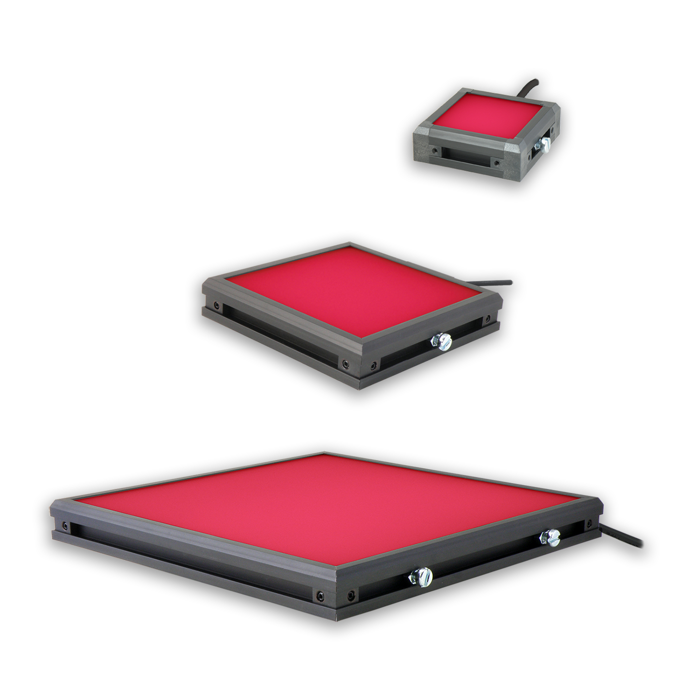
With Advanced Illumination’s BL2 Backlights, you will find improvements in intensity, uniformity, structural rigidity, and thermal efficiency all at the same cost as Ai’s original BL Backlights.
With this information in mind, it is useful to remember there is a direct correlation between light wavelength and penetration ability; hence, for the same material, the longer wavelength light in backlighting applications – such as red or IR – may penetrate more deeply than blue, for example.
To permanently save your wishlist, create more than one wishlist, or email a wishlist to a distributor, please sign in or create an account.
Structured light 3D scanning is renowned for its speed, outpacing many other scanning methods, largely due to its ability to project patterns and capture large amounts of data in a single pass. Unlike point-based techniques like laser scanning, which typically collect a single data point at a time, structured light scanners project a pattern across the surface of the object allowing the scanner to process much larger data-sets.
Structured light 3D scanning is more than a technology; it’s a gateway. It blends accuracy, speed, and versatility to make it the optimum choice in so many different applications. As structured light continues to evolve, its applications are only set to expand, solidifying its role as a staple in modern digital workflows.
Keeping in mind the varying impacts that wavelength and intensity from backlights can have on your inspection system, it can be difficult to know exactly what lighting solution is best for your application. Our team of experts at Ai are here to work through your challenges with you – and are committed to helping you find the most accurate solution for your machine vision needs. Contact us today to assist you in your backlighting application!
Backlight computer
From industrial design and quality control to cultural heritage preservation and healthcare. Learn more in our next 3D Scanning 101: Applications for Structured Light Scanning.
As a non-contact method, structured light is safe for delicate objects and can be used without risk to the operator or the subject.
It is important to note that part color has a different effect on contrast levels depending on whether we are inspecting opaque or semi-transparent objects. In the case of opaque objects, we are inspecting with reflected light rather than transmitted light (backlighting), so wavelength-specific color contrast is very important. When backlighting semi-transparent parts, color typically plays a minor role in wavelength-specific differential light transmission through an object, whereas the material’s composition, internal structure, and/or texture are significantly more influential in this regard.
This stems from the technology’s use of light rather than physical contact or potentially harmful radiation, as found in some other scanning methods. Since there is no need for direct contact, the risk of damaging delicate or fragile objects, such as historical artifacts, artworks, or biological specimens, is minimized.
Is having sufficient intensity the only solution when looking to penetrate materials in backlighting applications? If we consider the visible and near-visible light spectrum (Figure 3), we see that white, or human-visible light, ranges from 400 nm to about 700 nm in wavelength. UV light ranges from 400 nm down to about 200 nm, and IR light ranges from 700 nm up.
We work closely with our vendors to provide high-quality LED lighting for machine vision applications. Visit our PRODUCTS section to discover an LED lighting solution for your vision application and choose "CONFIGURE THIS LIGHT" to customize a light to meet your needs.
Back lightingphotography
The first step involves projecting a light pattern onto the object. The nature of the pattern can vary, but it’s essential for the system to recognize and analyze the deformations accurately.

Backlightlighting
Whether you’re new to structured light 3D scanning or a seasoned pro looking for a refresher, this multi-part series dives into a comprehensive look into what makes this technology trusted across various industries for its precision, versatility, and efficiency.
This is a critical consideration in human scanning applications like medical or special effects in film or television. These factors make structured light 3D scanning a go-to for applications where preserving the condition of the object and ensuring the safety and comfort of individuals are needed.
The core principle of structured light 3D scanning revolves around triangulation. By projecting a known pattern onto an object and capturing it from different angles, the system can calculate the depth and surface contours of the object with high precision.
In this example, we used BL040401-660 (Red) and BL040401-880 (Near IR) surface mount backlights on a semi-transparent, populated PCB (Figs. 4a and 4b, respectively) to test how well each wavelength penetrated the material. We see that the 880 nm IR light better defines the traces in the board than the 660 nm Red light. However, how do we know that the IR light wasn’t just more intense with respect to the camera – or even that the camera was more sensitive to IR light?
However, there are variations on the black-white silhouette theme – namely those applications requiring the light to differentially penetrate portions of the part. This could include applications that require locating a solid object of different composition or texture within another object, or identifying a liquid level in a package, for example. In this blog post, we will concentrate on differential backlight penetration and illustrate varying examples of where and why different wavelengths may be useful.
Another common backlighting application is verifying fluid fill-level in bottles. In this example, a colored glass bottle contains clear cologne. If we backlight with red, the most common color, we see that the light does not penetrate the bottle (Figure 6a). Based on the general assumption that a longer wavelength light penetrates better, we switch to IR 880 nm light; notice it still does not penetrate the bottle and its contents (Figure 6b). For the sake of completeness, we attempt blue, the shortest wavelength light; interestingly, it penetrates the bottle and contents well enough to verify the liquid fill height (Figure 6c)
In machine vision, backlighting is one of the most common and useful lighting techniques. It’s typically used for parts presence/absence, gauging, and orientation/location, particularly when coupled with pick-and-place or vision-guided robotics applications. However, incorporating backlighting into machine vision systems can be difficult, primarily because component placement geometry requires access to the part top and bottom (or front and back) for the camera and backlight.
A similar penetration trend can be observed in inspecting an incandescent light bulb filament. A series of images taken with 470 nm blue, 660 nm red, and 880 nm IR back lights (Figures 5a, 5b, 5c respectively) illustrate this point. Blue light does not penetrate the light bulb glass and diffuser coatings; the red light shows some filament detail; and ultimately, the IR light clearly produces the most useful inspection detail.


 Ms.Cici
 8618319014500