
Josh's Frogs Green Gro LED SPOTLIGHT Bulb (10 Watt) - green led spotlight
Battery does not appear to send any data on P1/P2 when battery test button is pushed; also doesn't appear like Milwaukee M18 Batteries support the long-press self-test diagnostic/LED flash codes anymore. Can't get them to appear on any battery year 2015+... [edit: Newer M18 FORGE batteries appear to have the functionality built in again]
Interested in discovering your recipe for growth and joining our team? Take a look at our career page for more information.
Philips products are sold through a global network of certified partners. Find partners in your region for more information about Philips LED grow lights.
CompactLED lighting price list
Philips GreenPower LED toplighting compact fits seamlessly in existing HPS infrastructure and trellis constructions; even between sprinklers. There are two smart options: either you choose to replace your existing HPS installation with a similar light output and consume 50% less power, or you choose to utilize the maximum CHP power available and increase your light output to 150% compared to current light level.
After removing 4 tamper-proof torx screws and popping the top off the battery top casing off, we're left with a simple circuit board connected to 5 pins and 10 batteries (5 sets of 2 cells). Did I say simple? (I might regret that later...)
Compactstriplight
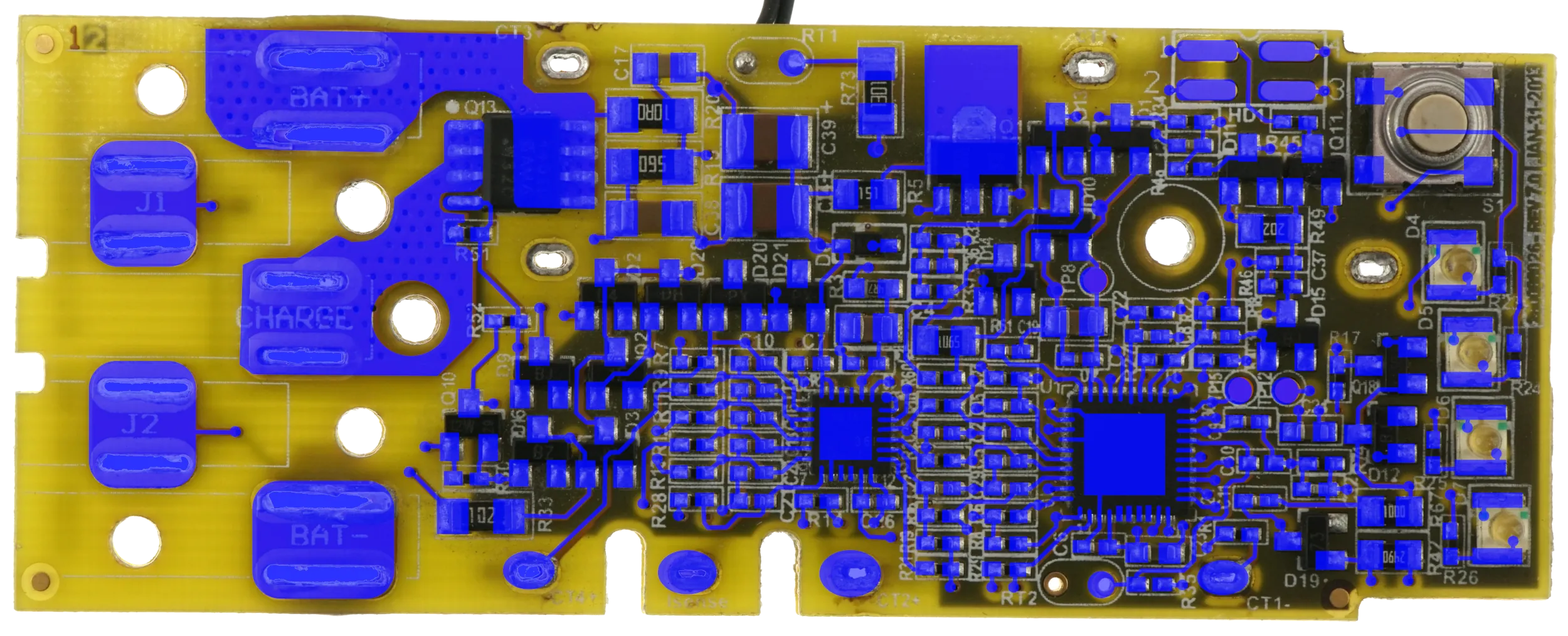
I've gone through and marked all the copper layers to the best of my abilities. You can download a lower-res version of the document I'm working off of here. (ZIP-XCF-Gimp, 30.1MB) I'm going to have to take a bit of a break on this project, but this should be enough info for you to start tracing connections without going to all the previous work. (Let me know if I messed up any of the connections!). And yes, I know I didn't dump firmware either...It is on my todo list! Enjoy!
2024-10-5: Another video from Tool Scientist. He explains things so much better than I can! Seems there is one small step yet until someone builds a 3rd party external balancer for these batteries. (PLEASE, if someone has done so, please let me know! I'll gladly build and test units if needed!) I've done manual balancing on 100's of these batteries to get them working again! And what was he working on that he created code to generate a balance byte? :) I guess we'll find out in future videos!
LEDVANCE - we advance light. As one of the world's leading providers in general lighting for professional lighting experts and consumers we offer a wide ...
CompactLED lights catalogue
CompactLED Downlight
2023-02-11 Update: Below is some data for anybody to pour over. Still not quite sure on bit order - scope is set for LSB (Least Significant Bit). First spreadsheet is the results of a 7 second capture on my scope, triggered by the communication line dropping in voltage when the battery gets plugged into the charger. Charger begins communication with an 0x55 handshake (Charger is RX and Battery is TX). Various data points about the batteries are included in the spreadsheet. Strangely, a lot of it looks very similar with the only major difference being an early shutdown in communication when the battery reports itself as already full. First byte might be a device ID. Second byte may be a command. Last byte is a checksum. In between?
Also realized I never linked to the other partially finished, related pages to this project. For more information on the Rapid Charger internals, CLICK HERE. For a similar (but not the same) partially completed teardown of a 5Ah battery, CLICK HERE. (the reference in the video above about the Renesas R7F0C901B2 microprocessor is what made me check for the links that I apparently never put up on this page.)
2nd/3rd Spreadsheet: I also tapped the SDA/SCL Communication lines between the BQ76925 and R7F0C901B2 MCU in addition to watching the P1/P2 Data lines. Unfortunately, my scope has a very limited capture time due to four channels and the increased resolution required for the I2C communication. This shows the data that is being requested by the R7F0C901B2 MCU, but not the actual data supplied by the BQ76925. I've included a couple pictures on the spreadsheet of register maps on the BQ76925 to help decode the data... Strangely, at least to me, VC4_CAL isn't requested and I only see requests for one battery cell voltage. (please correct me if I'm mis-interpreting data wrong)
I'll add this diagram to the page as well, since J1/J2 communication seems to be a popular request and that I think I finally have it decently diagramed. J2 seems to have a dual purpose;1) The Battery receives about 12VDC when connected to a charger (possibly also a tool?) This passes through R33 and 'wakes up' the MSP430 (assuming it is not already running). Battery then appears to pull voltage down [on J1], which signals to the charger that a battery has been connected and allowing communication to start.2) Communication appears to pass through D11 -> Q11. MSP430 Communication Pins 40 and 31 are pulled high by Resistor R45 and pulled low by Q11.3) I'm unsure what purpose the R48 connections serve at this point.
CompactLED TubeLight
There are a surprising number of M18 tools that don't seem to communicate with the battery... Course I'm dealing with mostly used/otherwise broken tools, so there is a possibility that there is something faulty there as well. M18 LED Flashlight, transfer pump, circular saw etc don't seem to communicate.
Find more words! Another word for, Opposite of, Meaning of, Rhymes with, Sentences with, Find word forms, Pronounce, Translate from English, Translate to ...
An industrial styled spotlight for both the wall or ceiling - perfect or both modern industrial rooms or classic cottage decor.
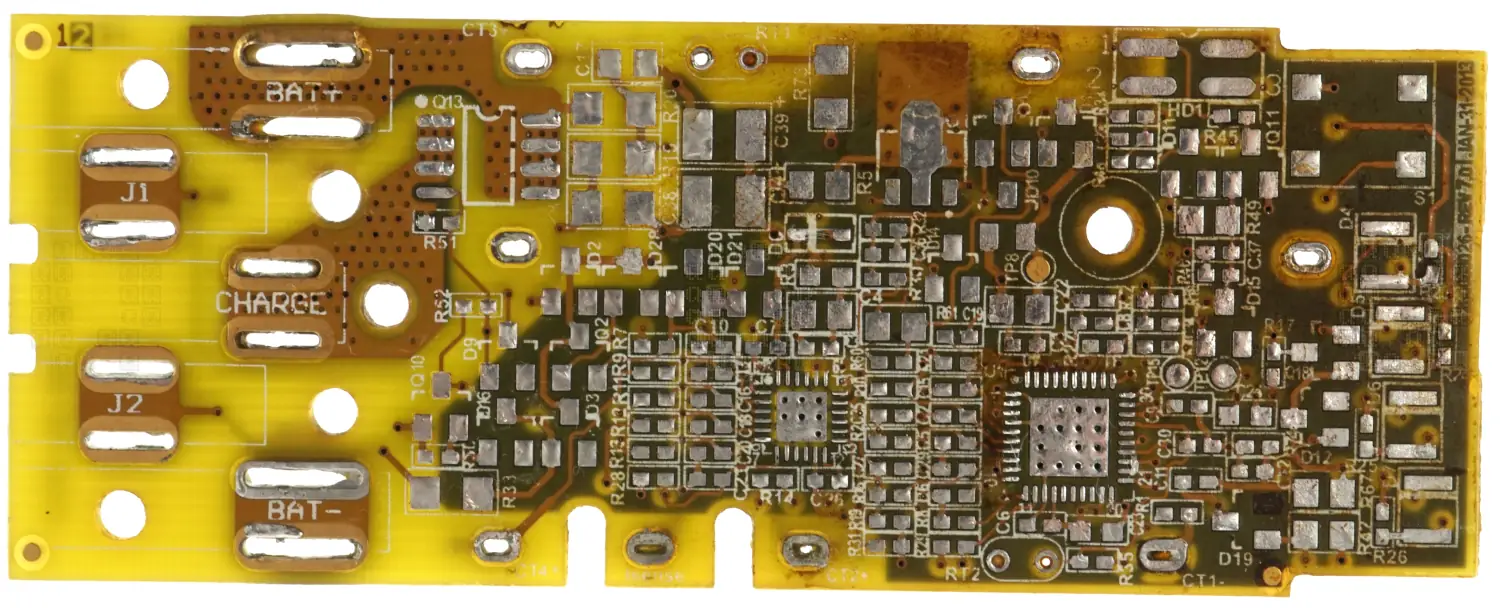
And back side of the PCB... Sorry, I really shouldn't have used that 300W Weller soldering iron on these... I don't have the proper tip for the wide terminals on my Hakko... [Another reminder to get this at some point.] I really need to get the coating off these boards.
Among various lighting options available, the small ring light has gained immense popularity for its versatility and efficiency. These compact ring lights offer ...
Philips GreenPower LED toplighting compact allows you to easily switch to LED lighting, replacing your existing HPS set-up, or building a new installation. The high light output of up to 2650 μmol/s or high efficacy of up to 3.7 μmol/J helps you effectively optimize crop growth, enhance crop quality and cut operational costs. With a wide beam or standard beam you can cater for any greenhouse height and the dimming possibility allows you to dim the grow lights to 10% of its maximum output to increase flexibility.
And one more diagram... This diagram shows the various signal wires and communication links between the MSP430 and the BQ76925. Finally have the Thermistors fit into the circuit as well!
The new S8 LED off-road light bar has a lightweight aluminum frame with amber backlighting to handle rugged trails. If you want ultimate customization options, ...
And as always, clicking on an image will give you a higher-res version! If you repost or further dissect this board, please link back to the original and let us know where we can read about your work!
And here are the UI circuit elements. It surprised me that they are using Q1 to turn the LEDs on and off; why would you use an extra IO Pin to cut power to LEDs? Would there be a leakage/voltage problem I'm missing? Switch input is nicely de-bounced in hardware, although there again I'm confused by the extra IO pin connected via R27... It seems wasted somehow; wouldn't a typical circuit use R27 to bias pin 33 towards VCC instead of connecting to an IO pin? There are direct connections from the 4 pin header to Pin 5 (Manual says 'Reset or nonmaskable interrupt input. Spy-Bi-Wire test data input/output during programming and test.') and Pin 37 (Manual says 'Selects test mode for JTAG pins on Port 1. The device protection fuse is connected to TEST. Spy-Bi-Wire test clock input during programming and test.') I really don't like seeing direct mentions about 'device protection fuses' on pin descriptions when I'd like to retrieve firmware at some point.
After a bunch more sanding, we're left with a decently clear view of Layer 2 on the PCB. We can see the ground/negative plane on the right hand side of the board.
2023-01-01: This project has been ongoing for a while... now its time to post some of this info and see what comes of it. I have access to several junk Milwaukee M18 batteries. Age varies a little. I thought it would be 'fun' to reverse engineer a battery just to see how it functions... That is until I actually opened the first one up and saw all the 0402 resistors and capacitors. Then it seemed like a 'fun-bad' idea. So here is the start of the first battery; Enjoy! (Reminder - Click on an image to get a larger version!)
Due to our broad assortment and dimming opportunities, you will be able to install any light level in a new greenhouse connecting 2, 3, or 4 Philips GreenPower LED toplighting compact on a trellis or use C-profiles instead. You can opt for a 645 to 780W grow light with an optimized performance, balancing light output and efficacy. Or you can choose one of our 520W solutions, utilizing half the power consumption of an HPS system.
Philips GreenPower LED toplighting compact comes in a standard beam for optimal efficacy and wide beam for excellent light distribution and uniformity in most greenhouse configurations including high wire-crops.
CompactCeiling Lights
2023-02-04: A couple interesting google patent links for M18 Batteries:BATTERY PACK INCLUDING AN ELECTRIC HARNESS AND METHOD OF MANUFACTURING THE SAME (PDF, 11 pages, 770KB).SYSTEM AND METHOD FOR CHARGING A BATTERY PACK (PDF, 9 pages, 1MB).HIGH - POWER CORDLESS , HAND - HELD POWER TOOL INCLUDING A BRUSHLESS DIRECT CURRENT MOTOR (PDF, 72 pages, 5.8MB).
Last byte of each message appear to be a Checksum. IE 0x81 + 0x20 + 0x00 + 0x00 = 0xA1 (Thanks again to Mick @ buyitfixit)
After a very tedious couple hours of de-soldering components and trying to measure each and every one, we're left with a board that looks like this; It needs some cleanup yet, but that will come shortly... I now have a BOM (PDF, 3 Pages, 29KB) that is surprisingly complete and a board that is still mostly intact - If you want something to look for I lost a total of one pad and loosened two more. The lost pad isn't connected to anything as far as I can tell.
I put this PCB under a decent camera (Sony A6300 with the FE 2.8/50 Macro lens) after removing the circuit board and de-soldering the connectors.
Multilayered Ring of Light ... The Multilayered Ring of Light spell is a new Incantation in the Shadow of the Erdtree expansion. It's learned in the Stone Coffin ...
After a soak in some solvents and a quick scrub with a brass bristled brush, we're left with a nice clear board. We've got two chips that took a bit of time to figure out what they were... [insert plenty of wasted time trying to get pictures of the poorly lasered markings and guessing of multiple digits (is that a B or an 8?; a 6, 5 or an 8?) - My wife finally arrived at the solution for U2 - Hooray for second opinions and excellent reading/deciphering skills!] U1 is a Texas Instruments MSP430G2744 Mixed Signal Microcontroller (Datasheet, PDF, 86 pages, 2.15MB). U2 is a Texas Instruments BQ76925 3 to 6 Series Cell Li-Ion Battery Monitor IC (Datasheet - PDF, 48 Pages, 6.10MB).
Philips GreenPower LED toplighting compact has been designed for easy installation. Specific snap brackets are available for safe operation distance from your screens.
December 7, 14 & 21, 2024. We invite guests to join us as we illuminate the night sky above our beautiful colonial capital.
Definitely glad to know I wasn't crazy or being downright stupid in not finding any communication happening between the tool and battery, though I'll have to confess I did miss the 12V/3V 'handshake' - I saw that the voltages were there, but never saw the handshake or saw them drop out. That and the complete miss on the battery amperage monitoring even though I clearly saw that it was supposed to be there on the sample designs. I just assumed Milwaukee chose to not implement it. Excellent work by the tool scientist... Now on to some new circuit designs!
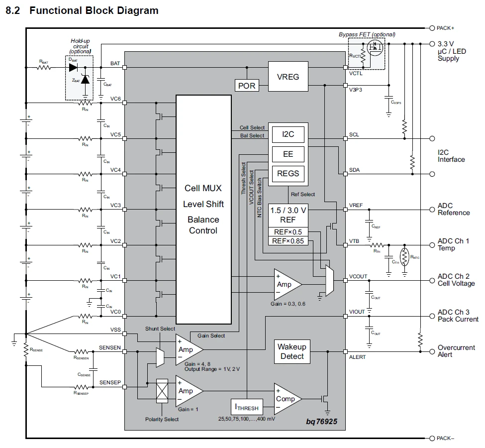
Its almost funny seeing that Milwaukee's battery uses an almost exact copy of this reference diagram from Texas Instruments' Application Report. (PDF, 29 Pages, 941kB) Only thing different I can see is the alert line which is unused by Milwaukee... Wonder why? (I didn't dive into the details on this pin yet...) I guess you can't improve on something that is perfectly designed!
Thanks to Mick @ buyitfixit for reminding me that when you measure a bit duration of 500us and calculate a baud rate of 2000 you probably shouldn't try to decode a serial stream with 1200 or 2400 baud no matter the what the datasheets say (or what common baud rates are).
Back side of the board... It was at this point that I noticed the tiny little numbers in the upper right hand side of the PCB (the dim 3 and 4). I then had to flip the board over and verify that there was indeed a 1 and 2 on the top side... Uh oh... (This is a 4 layer circuit board) I should also note here the text on the bottom of the board reading "280086026 Rev 7.0 Jan-31-2013"; as far as I can tell that is the same as what the front says.
Bright-field images are formed, if we use a small objective aperture to select only the directly transmitted beam of electrons. Dark-field images are formed, if ...
2023-09-12: Update: I have no affiliation with Tool Scientist, but he's taken the reverse engineering further than I had time to...
2023-02-03: Oh look! A handy guide from Texas Instruments on how to use the BQ76925 with the MSP430G2xx2. (PDF, 29 Pages, 941kB) Why do the circuit diagrams look familiar? It is almost like Milwaukee used a Texas Instruments reference design with tweaks!
JavaScript seems to be disabled in your browser. For the best experience on our site, be sure to turn on Javascript in your browser.
CompactLED TubeLight36 watt price
Philips GreenPower LED toplighting compact can be dimmed to 10% of its maximal photosynthetic photonflux in combination with the GrowWise Control System to improve the efficacy. This allows growers to dim the lighting for reasons of additional energy saving during peak hours or to mimic the dusk to dawn interval and enhance results for specific crops.
2023-01-16: Small update and work in progress notice: I've attached a small diagram of the BQ76925 Battery Monitoring Connections. This is one area that always puzzled me about these batteries: Was there cell balancing? The answer for this battery is a definite NO! (and this puzzles me...why not? I mean aside from cost?) 2023.2.1 Correction: Thanks to Ben C. for pointing out my mistake; It does appear as if the BQ76925 has the ability to balance cells. Current is controlled by R7/R9/R11/R12/R11. But the actual balancing is controlled by commands from the host MSP430. Every battery connection except BAT+ and CT1- are fully diagramed in this image. I am really confused about the purpose of D20/D21 though... [2023.2.1 note: I think I stumbled onto part of the voltage regulation circuit for the microprocessor. Not diagramed fully though. I really should have included the block diagram from the BQ76925. I'm including it here for reference.] I'm still confused by the difference in capacitor layout between the two diagrams and the actual Milwaukee design though.
And here is our first candidate for reverse engineering: a Milwaukee M18 48-11-1828 18VDC 54Wh / 3 Ah Battery Pack. (Hey its the first one I picked up... I was aiming for a 5Ah and missed somehow... Didn't actually look very close at what I grabbed until the PCB was already removed.) Serial: B41MD 028567. This particular battery doesn't seem to hold its charge properly (indicator lights go up to full when charging, but put it on a drill and spin it for a second, and the indicator now reads two bars.) Battery voltages appear nominal though. Wasn't really interested in the cells themselves, so left this area of investigation go for the time being.
CompactLED PANELLight
2023-01-28: Small update: Quick diagram of the charging control circuit. I needed to know which pin on the MSP430 controlled the charging circuit. Now you know too! Datasheet for 4401 P-Channel MOSFET (Datasheet, PDF, 8 pages, 181KB). Just as a reminder, RT2 is not populated and R29 is populated. (somehow I mis-labeled this resister on my BOM and the other board I have doesn't have RT2 or R29 on it... I need to dissect a couple more batteries to find a similar circuit board of similar vintage.) Now, I'm wondering how the battery knows a charger is connected...
Mar 20, 2017 — Over the ensuing decades, as the meaning of intoxication widened to include the effects of drugs as well as alcohol, so evidently did lit's ...
Same process on the other side of the PCB. We can see Layer 2 fairly nicely, although I will warn you that some of the vias aren't highlighted very well because of the ground plane on Layer 3... The larger copper area clustered around U1 appears to be the positive rail.
SYLVANIA LED light bars are put through rigorous quality testing to ensure premium quality and come with a Lifetime Limited Warranty.
Dimming will work reliable without the need of specific control cables. The GrowWise Control System can be used standalone or can be connected and controlled via your climate computer.
A quick sand with 400 grit sandpaper to take away the solder resist and silkscreen leaves us with most of the copper on Layer 1 visible. Now we need to get to the middle layers.


 Ms.Cici
 8618319014500