
LED Lighting Benefits - led & lighting
PERFORMANCE iN LIGHTING asymmetric optics generally have asymmetric light distribution on plane α with a point of maximum concentration. The axis passing through the point of maximum concentration and the point marked by the axis of the lamp is called the Imax axis. The light distribution on plane β, on the other hand, may be symmetric or asymmetric. An asymmetric optic may be symmetric in relation to one plane only. EXAMPLE Asymmetric optic code: Ayy/xx where A = Asymmetric yy = numeric value of the Imax angle. The Imax angle is the angle between axis A and the lmax axis. xx = the abbreviated name of the opening angle For example: Ayy/I – Ayy/M – Ayy/W – Ayy/EW. By convention, the beam opening of plane α is considered. For example: A30/M = Asymmetric axis with Imax 30° and Medium opening A45/I = Asymmetric axis with Imax 45° and Intensive opening In the presence of multiple asymmetric optics with the same lmax value and same beam opening range, it will be necessary to distinguish them by adding the numeric value of the beam opening at the end. For example: A45/M25 - A45/M40 Asymmetric optic name Type of optic Imax angle Acronyms Opening angle plane α A Numeric value of the Imax angle I 0° ÷ 20° M 21° ÷ 45° W 46° ÷ 75° EW > 75° Mandatory indications Additional indications Type of opening Description A1A2A3 Includes all asymmetrical optics from Narrow to Wide for Power LED ASWALW Includes all asymmetrical optics from Narrow to Wide for COB ASYMM Asymmetrical optic
EXAMPLE Asymmetric optic code: Ayy/xx where A = Asymmetric yy = numeric value of the Imax angle. The Imax angle is the angle between axis A and the lmax axis.
Grazing reflector optics stand out for their luminous emission that is typically parallel (grazing) to the installation surface (wall or ground). These optics are primarily used for architectural lighting with the purpose of designing patterns of light and they rarely have a functional use. A fundamental characteristic is the value of the α angle that identifies the value of the light beam aperture measured on the installation surface. Installation surface (wall) Installation surface (ground)
For optics for pedestrian crossings PERFORMANCE iN LIGHTING identifies those optics for lighting in the direction of their flow. They feature asymmetrical emission both on the α plane and on the β plane. EXAMPLE Acronym of optics for pedestrian crossings: Z/R where: Z = zebra (pedestrian crossing) R = right (for countries where driving is on the right) Two-way traffic One-way traffic
Sony STARVIS
PERFORMANCE iN LIGHTING elliptical optics are circular but differ from roto-symmetrical circular optics because the opening of the light beam on planes α and β is symmetric, but differs greatly between the two. The light distribution is highly elliptical.
To get a silicon layer on top of the sensor, it is necessary to build the chip the same way as a traditional front-illuminated sensor, but then place another layer of silicon substrate on top and flip the entire silicon sandwich over. After that comes the hard part. The original base layer of silicon, which is now on top, has to be thinned to make it act as a light-sensitive layer.
EXAMPLE Acronym of the road optics based on the L/H ratio: R/xxx where: R = road xxx = L/H value (e.g. 100 = 1.00) For example: R/075, R/100
Sony sensor
As you'd expect, putting the photodiode at the bottom of a well reduces the amount of light that reaches it, with some light bouncing off the wiring above, and some just not having the right angle to make it to the bottom of the well. Microlenses are used to reduce this problem (the human eye uses waveguides known as Muller cells), but a meaningful amount of light is still lost before it gets to the photodiode to be captured. Typical sensor fill factors -- the portion of light successfully captured -- range from 30% to 80%. By contrast, a back-illuminated sensor can have a fill factor of nearly 100%.
EXAMPLE Elliptical optic code: E α x β where: E = Elliptical α = Opening of the light beam on plane α expressed in degrees β = Opening of the light beam on plane β expressed in degrees
Silicon is both the substrate on which chips are built and the material that performs the magic of turning photon energy into electrical energy that can be used to create images. It is therefore the simplest solution to create the photosensitive areas in the substrate silicon and stack the electronics on top -- leaving openings in the wiring over each photosite (pixel) to allow light to pass through. As camera resolutions have increased, pixel sizes have decreased, especially in smartphones with their tiny sensors. The result is that more and more of the surface area of the sensor is covered by wiring, resulting in less and less light reaching the photosites. So there is a natural need to find a way to move the photosensitive region to the top of the chip, allowing it to gather more light.
For optics for pedestrian crossings PERFORMANCE iN LIGHTING identifies those optics for lighting in the direction of their flow. They feature asymmetrical emission both on the α plane and on the β plane. EXAMPLE Acronym of optics for pedestrian crossings: Z/R where: Z = zebra (pedestrian crossing) R = right (for countries where driving is on the right)
PERFORMANCE iN LIGHTING identifies those optics that generate a luminous emission with a symmetry of revolution about the A axis as circular optics. The opening angle of the beam is generally constant in all planes. The reflectors generating these optics generally have a circular opening. EXAMPLE Circular optic code: C/xx where: C = Circular xx = the abbreviated name of the opening angle For example: C/I - C/M - C/IW - C/MW -C/EW Multiple optics within the same range of opening will be distinguished by inserting the numerical value of the beam opening at the end. For example: C/IW46 - C/IW50 Circular optic name Type of optic Acronyms Opening angle plane α C I 0° ÷ 20° M 21° ÷ 45° IW 46° ÷ 60° MW 61° ÷ 75° EW > 75° Mandatory indications Additional indications Type of opening Opening angle α C1 30° ÷ 45° C2 25° ÷ 30° C3 20° ÷ 25° C4 15° ÷ 20° C5 10° ÷ 15° C6 0° ÷ 10°
Backsideilluminated
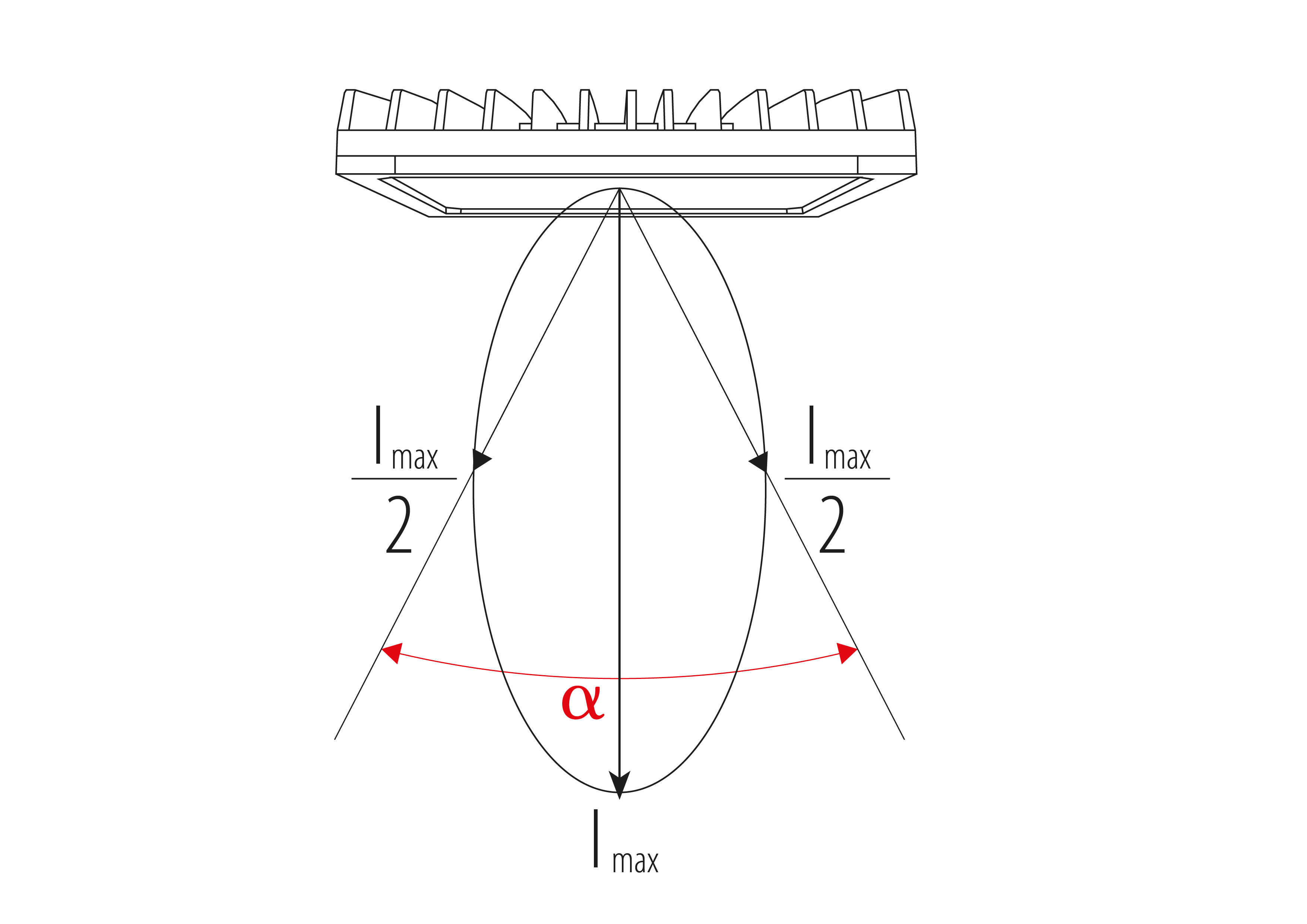
The Group's luminaires offer different types of optics depending on project requirements. The optic can be identified as the set of equipment designed to direct the light generated by a light source in a particular direction, thus determining the luminous emission of the luminaire itself.
Optical format
GEWISS is a key player on the market manufacturing solutions for home & building automation, energy protection and distribution systems, smart lighting and e-mobility.
Sony has already started sampling a stacked version of a BI chip with its Exmor RS, which is expected to ship in volume this year. As BI technology continues to improve, look for Sony to be one of the first companies to use it in their larger sensor cameras. The larger pixel size of APS-C and full-frame cameras allows a high fill factor even with traditional front-illuminated technology, but as BI gets cheaper and stacked systems allow additional features, expect it to begin to appear in mirrorless and DSLR cameras.
The Group's luminaires offer different types of optics depending on project requirements. The optic can be identified as the set of equipment designed to direct the light generated by a light source in a particular direction, thus determining the luminous emission of the luminaire itself. The diagram below identifies the data that will be contained in subsequent pages, regarding the opening angle of the beam. IMAX = maximum luminous intensity, i.e. the maximum intensity of the emitted light beam. Depending on this luminous emission, PERFORMANCE iN LIGHTING classifies optics in the following categories:
In the presence of multiple asymmetric optics with the same lmax value and same beam opening range, it will be necessary to distinguish them by adding the numeric value of the beam opening at the end.
With this classification PERFORMANCE iN LIGHTING identifies the light emission typology of the luminaires inside those series that contain models with direct, indirect and / or combined light emission. Name of symmetrical optics for luminaires with double light emission Type of optic Acronyms Typology of light emission S S/A Direct symmetrical light S/B Mainly symmetrical direct light S/C Evenly direct - indirect symmetrical light S/D Mainly symmetrical indirect light S/E Indirect symmetrical light
IMX811
PERFORMANCE iN LIGHTING identifies those optics that generate a luminous emission with a symmetry of revolution about the A axis as circular optics. The opening angle of the beam is generally constant in all planes. The reflectors generating these optics generally have a circular opening.
ExtremeTech is a federally registered trademark of Ziff Davis, LLC and may not be used by third parties without explicit permission. The display of third-party trademarks and trade names on this site does not necessarily indicate any affiliation or the endorsement of ExtremeTech. If you click an affiliate link and buy a product or service, we may be paid a fee by that merchant.
Sensor format
Multiple optics within the same range of opening will be distinguished by inserting the numerical value of the beam opening at the end.
The diagram below identifies the data that will be contained in subsequent pages, regarding the opening angle of the beam. IMAX = maximum luminous intensity, i.e. the maximum intensity of the emitted light beam.
For example: A30/M = Asymmetric axis with Imax 30° and Medium opening A45/I = Asymmetric axis with Imax 45° and Intensive opening
For road optics, PERFORMANCE iN LIGHTING identifies the optics that have a very broad beam spread on the β plane (usually greater than 120°), with the point of maximum emission on one of the adjacent planes to the latter, up to a maximum of 45°.
For PERFORMANCE iN LIGHTING, symmetric optics are ones with symmetric emission in relation to planes α and β. The symmetry between the two planes may be either identical (in this case we are dealing with optics with square light distribution) or different (optics with rectangular light distribution).
Sony IMX623 Datasheet
For PERFORMANCE iN LIGHTING, symmetric optics are ones with symmetric emission in relation to planes α and β. The symmetry between the two planes may be either identical (in this case we are dealing with optics with square light distribution) or different (optics with rectangular light distribution). EXAMPLE Symmetric optic code: S/xx where: S = Symmetric xx = the abbreviated name of the opening angle For example: S/I - S/M - S/W - S/EW By convention, we consider the beam opening of plane α. Multiple optics within the same range of opening will be distinguished by inserting the numerical value of the beam opening at the end. For example: S/W50 - S/W60 Symmetric optic name Type of optic Acronyms Opening angle plane α S I 0° ÷ 20° M 21° ÷ 45° W 46° ÷ 75° EW > 75° Mandatory indications Additional indications Type of opening Description S1S2 Includes all symmetrical optics from Narrow to Wide for Power LED SNSMSW Includes all symmetrical optics from Narrow to Wide for COB ARRAY Free distribution MEDIUM Medium beam diffuser OPALMICRO Wide beam diffusers SYMM Symmetrical optic
Grazing reflector optics stand out for their luminous emission that is typically parallel (grazing) to the installation surface (wall or ground). These optics are primarily used for architectural lighting with the purpose of designing patterns of light and they rarely have a functional use. A fundamental characteristic is the value of the α angle that identifies the value of the light beam aperture measured on the installation surface.
Better light sensitivity is just the beginning of what backside illumination makes possible. Sony has shown that BI technology allows creating a sensor from a stack of chips instead of a single chip -- so that the top chip can be optimized for capturing the light and the ones underneath can do the signal processing. A stacked design allows for additional processing at the pixel level without reducing the sensor's light sensitivity. Recent advances in through-silicon vias (TSVs; interconnects between a 3D stack of chip dies) have made this type of layering possible. This stacking is the same technology that is used in multi-layer memory chips, so it is getting significant investment.
By convention, we consider the beam opening of plane α. Multiple optics within the same range of opening will be distinguished by inserting the numerical value of the beam opening at the end.
APS-C

Light bouncing around inside the electronics can also cause other problems such as vignetting and crosstalk. Thus a design which puts the photodiodes on top is clearly desirable. Having the photosensitive area on the side of the chip facing the light also dramatically improves the angular response of the sensor. No longer does light have to be aimed "down the well" of the pixel, but it can strike it from nearly any angle.
PERFORMANCE iN LIGHTING asymmetric optics generally have asymmetric light distribution on plane α with a point of maximum concentration. The axis passing through the point of maximum concentration and the point marked by the axis of the lamp is called the Imax axis. The light distribution on plane β, on the other hand, may be symmetric or asymmetric. An asymmetric optic may be symmetric in relation to one plane only.
The magic that makes camera sensors possible is also what makes them difficult to build with the receptors on top. Because silicon is both the substrate for the sensor chip and the light-sensitive material, it wants to be both at the top and the bottom of the sensor at the same time. Traditional sensor designs simply start with the silicon and pile everything else on top. That allows for a single, relatively thick, layer of silicon and a straightforward manufacturing process.
With this classification PERFORMANCE iN LIGHTING identifies the light emission typology of the luminaires inside those series that contain models with direct, indirect and / or combined light emission.
PERFORMANCE iN LIGHTING elliptical optics are circular but differ from roto-symmetrical circular optics because the opening of the light beam on planes α and β is symmetric, but differs greatly between the two. The light distribution is highly elliptical. EXAMPLE Elliptical optic code: E α x β where: E = Elliptical α = Opening of the light beam on plane α expressed in degrees β = Opening of the light beam on plane β expressed in degrees For example: E 10°x45°
Omnivision helped pioneer the use of BI sensors in 2007, but until recently they have been too expensive for production use. Sony's Exmor R in 2009 was one of the first production sensors to use back-illumination -- nearly doubling its low-light sensitivity compared to other similar chips. Back-illumination broke into the mainstream when it was used in flagship phones including the Apple iPhone 4 and the HTC EVO 4G.
For road optics, PERFORMANCE iN LIGHTING identifies the optics that have a very broad beam spread on the β plane (usually greater than 120°), with the point of maximum emission on one of the adjacent planes to the latter, up to a maximum of 45°. Road lighting based on L/H ratio that can be found in road lighting systems, where: L: distance between the optical axes of the luminaire and the part of the area furthest from it with its own requirements. H: height of installation of the luminaire. EXAMPLE Acronym of the road optics based on the L/H ratio: R/xxx where: R = road xxx = L/H value (e.g. 100 = 1.00) For example: R/075, R/100 Name of the road optics based on the L/H ratio: Type of optic Acronyms Description SR 075 Optic for L/H fino up to 0,75 (0,5 ≤ L/H ≤ 0,875) 100 Optic for L/H pari of 1 (0,875 ≤ L/H ≤ 1,125) 125 Optic for L/H pari of 1,25 (1,125 ≤ L/H ≤ 1,375) 150 Optic for L/H pari of 1,5 (1,375 ≤ L/H ≤ 1,625) Mandatory indications Additional indications Acronyms Description HUGE Optics for wide road geometries WIDE Optics for medium road geometries ST1 Optics for medium-wide road geometries CYCLE Optics for pedestrian crossings
Olympus has demonstrated how a stacked (it calls it 3D) architecture can create new possibilities with its research prototypes of a BI sensor, with a nearly perfect shutter that it calls a "global" shutter. Like a rolling shutter the global shutter can work nearly instantly and without any moving parts, but avoids artifacts by placing the read out electronics on a lower layer behind a shield. Since it takes time to read all the data from a sensor, a rolling shutter can create smearing or other artifacts because the sensor is still actively receiving photons while the voltages are being read. The Olympus design transfers all of the charge off the sensor at once -- to the lower, shielded layer -- where they can then be read out accurately.
If a sensor was only a layer of photosensitive silicon, it wouldn't matter much which side was up. A pixel is a lot more than just the photodiode, however. It typically includes transistors and wiring for amplifying the charge, transferring it to the signal processing portion of the chip, and resetting itself between frames. Those electronics get placed on top of the silicon layer, partially obscuring it from the light and resulting in a well-like appearance for a typical pixel.


 Ms.Cici
 8618319014500