
Improved Accuracy and Resolution Using Point Source ... - best point source light mount
The optical setup for BF reconstruction is similar to an OPT system1,37,38 except for two main adjustments: (1) a translation stage is required to scan the sample along the optical axis or to scan the detection optics along the sample; (2) the illumination numerical aperture should match that of the detection: \(NA_{ILL} = NA_{DET}\). This second point is recommended to maximize the resolution of the microscope, which according to Abbe is \(\frac{\lambda }{{NA_{ILL} + NA_{DET} }}\), and consequently to obtain reconstructions with higher-contrast.
Fieramonti, L. et al. Time-gated optical projection tomography allows visualization of adult zebrafish internal structures. PLoS ONE 7(11), e50744 (2012).
Three-dimensional imaging of a transgenic pEXP7:YC3.6 Arabidopsis thaliana seedling. Transverse (a) and lateral (b) sections of root tip (mature zone) acquired with bright-field multi-view reconstruction. Transverse (c) and lateral (d) sections acquired with bright-field reconstruction (grey) and LSFM (green). Maximum intensity projection of the LSFM stack, combined with the minimum intensity projection of the bright-field reconstruction (e). Detail of panel e, showing the outgrowing part of the root-hair epidermal cells (f). Three-dimensional rendering of the reconstructed bright-field volume, combined with LSFM. Scale bar: 100 µm.
In order to obtain optical sectioning, we acquired multiple views of the specimen separated by an angle Δα and at each angle we collected a stack of images with sampling steps Δz. The different stacks were fused together to create a single reconstruction of the sample. We estimated the required number N of views by looking at the system OTF (Fig. 1b). Considering that, in paraxial approximation, the angle θ subtended by the OTF is approximately the system numerical aperture \(NA = n sin\theta \approx n\theta\) (where n is the index of refraction), we chose to acquire the views at an angle step of \(\Delta \alpha = \theta\) so that the maximum of each OTF overlapped with the minimum of the adjacent one. In this case, the number of acquired views resulted in \(N = \frac{2\pi }{{\Delta \alpha }} = \frac{2\pi n}{{NA}}\). One could exploit the symmetry of the OTF and acquire only \(\frac{N}{2}\) views around 180°, however in presence of scattering34,35,36 the acquisition of the sample around full 360° provided a more resolved reconstruction.
Some common machine vision lighting techniques include on-axis lighting, dark field lighting, spot lighting, bar lights, and backlighting. These techniques are used based on the specific requirements of the inspection task and the features of the object being inspected.
Explore our top picks for vision lighting products that are recommended for enhancing machine vision capabilities. These products have been carefully selected based on their performance, reliability, and compatibility with various machine vision systems.
Alanentalo, T. et al. Tomographic molecular imaging and 3D quantification within adult mouse organs. Nat. Methods 4, 31–33 (2007).
The Illuminati Join Application Form is a streamlined solution designed to simplify the process of joining the exclusive Discord channel "Illuminat...
When setting up machine vision lighting, factors to consider include selecting the appropriate lighting technique, determining the required light intensity and color, considering the object’s surface properties, and understanding the environmental conditions in which the inspection will take place.
[uncountable, countable] light or a place that light comes from. Extra Examples Most of the illumination came from candles. The skylights are designed to ...
Dark field lighting is a technique where the light source is positioned at an angle away from the camera’s optical axis. It creates contrast by illuminating the object from the side, highlighting surface imperfections and irregularities.
Machine vision lighting plays a crucial role in solving complex inspection tasks by providing the necessary illumination to capture clear images. By manipulating lighting angles, intensity, and color, it becomes possible to highlight specific features and enhance image contrast, enabling accurate analysis and detection of defects or anomalies.
The technique performs well also at higher NA. An example of reconstruction at NA = 0.3 with 10× magnification is shown in Supplementary Fig. 2. Here the diffraction artifacts in standard OPT are much stronger and a strategy for extending the depth of field22,27,28 would be in any case required. However, the focus of the present paper is to image an entire sample in a single measurement, which is demonstrated at lower magnification.
All methods were carried out in accordance with relevant guidelines and regulations. Zebrafish (Danio rerio) were maintained at the zebrafish facility, University of Milan, Via Celoria 26—20133 Milan, Italy (Aut. Prot, n. 295/2012-A—20/12/2012 for the breeding, growth and use of zebrafish, released by the Azienda di Tutela della Salute, ATS Città metropolitana di Milano). All experimental procedures were performed according to the international (EU Directive 2010/63/EU) and national guidelines (Italian decree No 26 of the 4th of March 2014). Embryos were staged and used until 5 days post fertilization, a time windows in which zebrafish is not considered an animal model according to national guidelines (Italian decree No 26 of the 4th of March 2014). All procedures to minimize stress and pain of the embryos were applied. Embryos were anaesthetized with 0.016% tricaine (Ethyl 3-aminobenzoate methanesulfonate salt, Sigma-Aldrich) before proceeding with experimental protocols.
To achieve this, the proper lighting setup is essential. The nature of the light used is crucial as it affects the accuracy of the recognition process. Different objects and surfaces may require close proximity lighting or light from behind to enhance their contrast and visibility. Wavelengths of light can also be manipulated to improve object recognition.
Chen, L. et al. Remote focal scanning optical projection tomography with an electrically tunable lens. Biomed. Opt. Express 5(10), 3367–3375 (2014).
Miao, Q. et al. Resolution improvement in optical projection tomography by the focal scanning method. Opt. Lett. 35, 3363–3365 (2010).
2019917 — The most basic distinction between the two is that white LED grow lights contain a balanced light spectrum that cannot be changed or adjusted.
van der Horst, J. & Kalkman, J. Image resolution and deconvolution in optical tomography. Opt. Express 24(21), 24460–24472 (2016).
Book a consultation with our expert to explore how AI solutions could fit your unique business needs. Whether you’re curious or uncertain, we’re here to discuss and guide you.
EFFILUX offers powerful LED bar lights with flexible optical, electronical, mechanical designs to fulfill the needs of different machine vision ...
If you want to capture clear and well-illuminated images, try positioning the light source in front of the object. Front lighting is a popular technique in machine vision solutions and can greatly enhance image quality.
Cheddad, A., Svensson, C., Sharpe, J., Georgsson, F. & Ahlgren, U. Image processing assisted algorithms for optical projection tomography. IEEE Trans. Med. Imaging 31(1), 1–15 (2012).
When selecting vision lights, it’s crucial to consider their ability to accurately recognize and classify objects. Object recognition and classification play a vital role in machine vision applications.
First, the type of light source used is crucial. Diffuse lighting can minimize glare and shadows, while back lighting can enhance surface features.
With these recommended vision lighting products, you can enhance the performance of your machine vision system, ensuring accurate and reliable detection, inspection, and measurement.
Longer lifespan: LED lights have a significantly longer lifespan compared to traditional lighting sources, reducing maintenance costs and downtime.
Ring LightA ring light is a circular light source that surrounds the camera lens, providing uniform illumination for close-up imaging.
Bassi, A., Schmid, B. & Huisken, J. Optical tomography complements light sheet microscopy for in toto imaging of zebrafish development. Development 142, 1016–1020 (2015).
Arranz, A. et al. In-vivo optical tomography of small scattering specimens: time-lapse 3D imaging of the head eversion process in Drosophila melanogaster. Sci. Rep. 4, 7325 (2014).
Then, stacks acquired at the different angles are resliced into planes (xz) which are orthogonal to the rotation axis. The z location of the center of rotation is found by maximizing the contrast of the reconstruction at different possible zC. The contrast is calculated as the energy (sum) of all the frequency components obtained by numerically Fourier transforming (fft2 function in the Python module numpy) the reconstruction, excluding the DC component.
As described and characterized by Trull et al.24, the diffraction of light in OPT causes space-variant tangential blurring that increases with the distance from the rotation axis. We clearly observe these artifacts when imaging structures that are just hundreds of microns away from the rotation axis. This effect is shown in the completely distorted reconstruction (Fig. 2a, blue arrow) of a root hair of Arabidopsis thaliana, which is c.a 200 µm away from the rotation axis (located at the center of the OPT reconstructed section in Fig. 2a). In Fig. 2, the sample was embedded in a tube (see Material and Methods) that is visible in the OPT reconstruction due to the presence of a small amount of scattering which causes light attenuation. The size of the tube can be used as a benchmark to assess the presence of space-variant blurring. We observe that the higher the distance from the center of rotation, the more blurred the border of the tube is in the OPT reconstruction. When applying the multi-view approach, the sample is reconstructed correctly in the entire field of view, avoiding the diffraction artifacts (Fig. 2b). However, as expected, by simply overlapping (sum) the views acquired at different angles, the image is overall blurred. In order to increase the quality of the reconstruction we used a deconvolution approach based on the Wiener or Lucy Richardson methods (see Material and Methods). In this way, the contrast and resolution are significantly improved leading to the observation of the Arabidopsis section at single cell detail (Fig. 2c). This improvement comes at the expense of higher noise, and in order to fully exploit the capabilities of the method a systematic study on deconvolution and regularization should still be carried out. It is worth noting that in case of highly diffusive samples the technique would be able to reconstruct only the outermost part of the specimen with artifacts given by the diffusion of light. Therefore, the method should be applied to translucent samples (as it is the case for zebrafish embryos and Arabidopsis roots), chemically cleared samples, or it should be combined with more advanced methods to reduce the effect of diffusion34,35,39.
Multimodal acquisition (bright-field/fluorescence) is performed alternating the LED (for trans-illumination) and the laser (for LSFM). After each axial scan required for bright-field acquisition, a second axial scan is repeated for LSFM acquisition. To this end two custom-made mechanical shutters are used to alternate the illuminations.
Kumar, V., Chyou, S., Stein, J. V. & Lu, T. T. Optical projection tomography reveals dynamics of HEV growth after immunization with protein plus CFA and features shared with HEVs in acute autoinflammatory lymphadenopathy. Front. Immunol. 3, 282 (2012).
Flexible SolutionsWith various lighting options available, machine vision applications can be tailored to specific requirements, allowing for versatility and adaptability.
In machine vision applications, lighting plays a crucial role in achieving accurate and reliable results. Proper lighting is essential for enhancing contrast, reducing image noise, and ensuring consistent illumination across the field of view.
Machine vision lighting refers to the use of artificial lighting techniques and equipment to enhance the visibility and quality of images captured by machine vision systems. It is a crucial aspect of successful machine vision applications.
In this article, we will take you on a journey through the intricacies of vision lights, providing you with the knowledge and tools to elevate your machine vision game.
Chen, L. et al. Mesoscopic in vivo 3-D tracking of sparse cell populations using angular multiplexed optical projection tomography. Biomed. Opt. Express 6, 1253–1261 (2015).
BacklightBacklights are positioned behind the object being inspected, creating a silhouette effect that enhances contrast and highlights edges.
On the other hand, the system required for BF reconstruction is also commonly present in multi-view LSFM microscopes, which allow translation and rotation of the specimen. Therefore, we performed our analysis on a LSFM microscope equipped with a Köhler illuminator for trans-illumination. In particular we used a 4× magnification (NA = 0.13) in the detection path: at this magnification and NA, the artifacts given by the diffraction are already present and significantly compromise the standard OPT results (Fig. 2a).
Boot, M. J. et al. In vitro whole-organ imaging: 4D quantification of growing mouse limb buds. Nat. Methods 7, 609–612 (2008).
McGinty, J. et al. In vivo fluorescence lifetime optical projection tomography. Biomed. Opt. Express 2(5), 1340–1350 (2011).
Mayer, J., Robert-Moreno, A., Sharpe, J. & Swoger, J. Attenuation artifacts in light sheet fluorescence microscopy corrected by OPTiSPIM. Light Sci. Appl. 7, 70 (2018).
Consider factors like application requirements, working distance, and optical considerations to select the most suitable lighting technique for your machine vision system.
Diffuse LightingDiffuse lighting provides uniform illumination by scattering light in multiple directions, reducing shadows and reflections.
One of these challenges is the presence of shadows, which can obscure important details and affect the accuracy of image analysis. To overcome this, we need to explore shadow removal techniques that can effectively enhance the visibility of objects.
In this section, we will delve into the key points of inspection and defect detection, object recognition and classification, and dimension measurement.
Another challenge is the issue of glare and reflections, which can distort the captured images and make it difficult to extract relevant information. In order to address this, it is crucial to implement techniques that can reduce glare and reflections, such as using polarizers or adjusting the angle of illumination.
In conclusion, mastering machine vision lighting is crucial for achieving accurate and reliable results in various applications. By understanding the principles and techniques, one can choose the right lighting solution and apply it effectively for different vision tasks.
For accurate dimension measurement, it’s important to ensure proper calibration of your measurement tools and use a consistent lighting setup throughout the process. At our company, we understand the significance of precision and efficiency in dimension measurement.
Dome lights: These lights provide uniform illumination from all directions, eliminating shadows and enhancing image clarity.
Choose between various types of vision lights to enhance your machine vision system. When it comes to machine vision lighting techniques, there are several options to consider. Here are five types of vision lights that can help you achieve optimal results:
Dome LightMachine Vision
Choosing the right machine vision lighting solution is crucial for achieving accurate and reliable results in machine vision applications. By understanding the importance of lighting and utilizing appropriate techniques, the full potential of machine vision can be realized.
Calisesi, G., Candeo, A., Farina, A. et al. Three-dimensional bright-field microscopy with isotropic resolution based on multi-view acquisition and image fusion reconstruction. Sci Rep 10, 12771 (2020). https://doi.org/10.1038/s41598-020-69730-4
Light intensity refers to the brightness of the lighting source, and it should be adjusted according to the specific application requirements. The angle at which the light hits the object being inspected affects the visibility of certain features and can help enhance contrast.
Arabidopsis thaliana seedling preparation was carried out accordingly to Candeo et al.43,44. and Romano Armada et al.45. Briefly, seeds of Arabidopsis thaliana Col-0 transformed with pEXP7:YC3.6 were surface sterilized by vapour-phase sterilization and plated on MS/2 medium supplemented with 0.1% (w/v) sucrose, 0.05% (w/v) MES, pH 5.8 adjusted with KOH and solidified with 0.8% (w/v) plant agar (Duchefa, The Netherlands). After stratification at 4 °C in the dark for 2–3 days, seeds were transferred to the growth chamber with 16/8 h cycles of light (70 µmol m−2 s−1) at 24 °C.
Bryson-Richardson, R. & Currie, P. Optical projection tomography for spatio-temporal analysis in the zebrafish. Methods Cell Biol. 76, 37–50 (2004).
Proper placement of the lighting is essential to ensure optimal illumination and minimize shadows or glare. By carefully considering these factors, we can optimize the performance of machine vision systems, improving their ability to accurately detect and inspect objects.
To accurately reconstruct the data, the position of the rotation axis must be determined at pixel resolution. We propose a straightforward method based on two processing steps to locate the rotation axis, both in x and z, assuming that the latter is parallel to the y axis (as in Fig. 1a).
Once the rotation axis is defined we process each plane independently, following an approach that has been proven to work properly in multi-view reconstruction of LSFM data in zebrafish47 and offers the possibility to be accelerated using graphics processing units (GPU), potentially providing the results in real time. Each xz plane is rotated around (xC, zC), by its angle view, and summed to the other views. In total, N different views are summed (N is the number of acquired image stacks around 360°) and the resulting image is divided by N. This mean image is the reconstructed plane. If deconvolution is applied, each xz plane is de-convolved before the sum. For deconvolution we used the theoretical point spread function (PSF) of the microscope. This is generated considering the numerical aperture of the lens, creating the corresponding Ewald sphere33, and calculating the absolute value squared of its 3D Fourier transform. For plane by plane processing, a two dimensional PSF is extracted from its three dimensional counterpart by slicing it in its central section. Deconvolution is then performed using the Wiener or Lucy Richardson filtering in the Python package scikit-image.
Monochrome compatibility: LED lights can emit a narrow spectrum of light, making them suitable for monochrome cameras that require specific wavelengths for optimal image capture.
In this discussion, we will explore recommended vision lighting products that are designed to meet the specific requirements of machine vision systems.
Bassi, A., Fieramonti, L., D’Andrea, C., Mione, M. & Valentini, G. In vivo label-free three-dimensional imaging of zebrafish vasculature with optical projection tomography. J. Biomed. Opt. 16, 100502 (2011).
Reconstruction of a transverse section of an Arabidopsis thaliana root using Optical Projection Tomography (a), bright-field multi-view reconstruction (b) and bright-field multi-view deconvolution (c). For (c, d), 45 views around 360°, with 8° spacing were used. The presence of spatially variant artifacts in OPT is shown with the blue arrow. The red arrows indicate the thickness of the reconstructed plastic tube far from the rotation center of the OPT reconstruction. Scale bar: 100 µm.
The sample is rotated by \(\Delta \alpha\) and the previous points are repeated for multiview acquisition. Typically the angle \(\Delta \alpha\) is chosen so to have a full 360° rotation after N + 1 rotation steps.
Trull, A. K. et al. Point spread function based image reconstruction in optical projection tomography. Phys. Med. Biol. 62(19), 7784 (2017).
Wavelength control: LED lights can be easily adjusted to emit specific wavelengths, allowing for precise illumination tailored to the application.
According to Globe news wire report the key players in the market include Advanced Illumination Inc., EFFILUX, Moritex Corporation, National Instruments Corporation, Omron Microscan System, Inc., Cognex Corporation, ProPhotonix Limited, Smart Vision Lights, Spectrum Illumination, and TPL Vision.
Armada, N. R. et al. In vivo light sheet fluorescence microscopy of calcium oscillations in Arabidopsis thaliana. Methods Mol. Biol. Calcium Signal. 10, 87–101 (2019).
You can effectively handle varying surface materials by adjusting the lighting setup and using appropriate filters and diffusers. When dealing with different materials, it’s important to consider their reflective properties and adjust the lighting angle accordingly. Here are some tips to help you tackle the challenges posed by varying surfaces:
The sample is translated along the optical axis and images are continuously acquired by the camera. The velocity of the linear stage is synchronized with the acquisition so that every captured image corresponds to a linear step of Δz.
Dark field lighting
Backlighting is a powerful technique that can provide precise and reliable results in machine vision applications, ensuring accurate detection and analysis of objects.
To ensure accurate inspection and defect detection, you’ll need to carefully select the appropriate vision lights for your machine vision system. Vision lights play a crucial role in providing the right illumination for imaging applications. Here are some key considerations to keep in mind:
Bestillumination machine vision
It allows the machine vision cameras to effectively capture and analyze images, enabling accurate object detection, recognition, and measurement.
The idea behind OPT is to acquire images (or projections) of the sample from different orientations. Similarly to X-ray CT the sample is then reconstructed using a back-projection algorithm23. However, this algorithm assumes that the light beam propagates straight through the sample: in X-ray CT the straight propagation is given by the high frequency of the radiation, whereas in OPT we can consider a straight propagation of light only within the depth of field of the system. Since the depth of field scales with the inverse of the second power of the Numerical Aperture (NA), the assumption is valid only at low NA (c.a < 0.1) which typically corresponds to a low magnification (1×, 2×). At higher NAs, artifacts due to the diffraction of light are present24. One way to attenuate these artifacts consists in limiting the NA of the microscope (e.g. by inserting a diaphragm at the back focal plane of the detection objective), but this also limits the resolution. Another way to mitigate this effect is to incorporate a spatially variant deconvolution in the reconstruction algorithm24,25. To drastically remove the diffraction artifact, some methods based on the extension of the depth of field have been proposed21,26,27,28. For each projection, the sample is scanned at different positions (up to 100) along the optical axis, and the acquired stack of images is merged into a single entirely focused projection29. Yet, this come at the expenses of the number of acquired images, since the process must be repeated for each projection (up to 1,000 angles within 360° rotation).
2021115 — When someone says those lights are bright, what is the first thing that comes to mind? Most people associate the word bright with the ...
Fieramonti, L. et al. Quantitative measurement of blood velocity in zebrafish with optical vector field tomography. J. Biophotonics 8(1–2), 52–59 (2015).
Backlighting involves positioning a light source behind the object being inspected, creating a silhouette effect that highlights any defects or irregularities.
Reduced NoiseAdequate lighting minimizes noise and improves the signal-to-noise ratio, leading to more reliable and consistent results.
Open Access This article is licensed under a Creative Commons Attribution 4.0 International License, which permits use, sharing, adaptation, distribution and reproduction in any medium or format, as long as you give appropriate credit to the original author(s) and the source, provide a link to the Creative Commons license, and indicate if changes were made. The images or other third party material in this article are included in the article’s Creative Commons license, unless indicated otherwise in a credit line to the material. If material is not included in the article’s Creative Commons license and your intended use is not permitted by statutory regulation or exceeds the permitted use, you will need to obtain permission directly from the copyright holder. To view a copy of this license, visit http://creativecommons.org/licenses/by/4.0/.
Front lighting, on the other hand, involves illuminating the object from the front, providing a clear view of its surface features.
Nagai, T., Yamada, S., Tominaga, T., Ichikawa, M. & Miyawaki, A. Expanded dynamic range of fluorescent indicators for Ca2+ by circularly permuted yellow fluorescent proteins. Proc. Natl. Acad. Sci. 101(29), 10554–10559 (2004).
Automation is another important consideration, as some lighting techniques may be more compatible with automated systems.
G.C. and A.B designed the experiments. G.C., A.B., C.D., A.Ca, A.F., V.M. and G.V. acquired and analyzed the data, A.Co. and A.P. prepared the samples and developed the imaging protocol. A.B. wrote the manuscript.
A collection of light diffusing films designed to allow light through while cutting glare and protecting your home or office's valuable furnishings.
Zebrafish AB strains obtained from the Wilson lab (University College London, London, UK) were maintained at 28 °C on a 14 h light/10 h dark cycle. The zebrafish transgenic Tg(kdrl:GFP) was used for fluorescence imaging. Embryos were collected by natural spawning, staged according to Kimmel and colleagues, and raised at 28 °C in fish water (Instant Ocean, 0.1% Methylene Blue) in Petri dishes, according to established techniques. After 24 hpf, to prevent pigmentation 0.003% 1-phenyl-2-thiourea (PTU, Sigma-Aldrich, Saint Louis, MO, USA) was added to the fish water. Embryos were washed, dechorionated and anaesthetized, with 0.016% tricaine (Ethyl 3-aminobenzoate methanesulfonate salt; Sigma-Aldrich, before acquisitions. During imaging, the fish were restrained in FEP (Fluorinated ethylene propylene) tubes37.
Additionally, the type of vision camera being used should be considered. Different cameras may have different requirements for lighting. For example, a color camera may require specific lighting conditions to accurately capture colors.
Huisken, J., Swoger, J., Del Bene, F., Wittbrodt, J. & Stelzer, E. H. Optical sectioning deep inside live embryos by selective plane illumination microscopy. Science 305, 1007–1009 (2004).
When it comes to effective machine vision illumination, there are three key techniques that we need to consider: backlighting, front lighting, and ring lighting.
Experimental setup for multi-view bright-field reconstruction: an LED (530 nm) illuminates the sample, the transmitted light is collected by a detection optical system and a camera. The sample is mounted on a translation and a rotation stage to be scanned and rotated around 360°. A stack of images is acquired in each angular position while scanning the sample (a). Scheme of the Optical Transfer Function of the microscope (b, upper panel). Acquiring multiple views is equivalent to rotating the OTF and sampling different spatial frequencies (b, lower panel). Reconstruction of the transverse section of a sample (Arabidopsis thaliana) using a single view (0°), 10 views (covering 60° in total) and 60 views (covering 360°), each with a spacing of 6°. The illumination and detection numerical aperture is NA = 0.13 (c). Scale bar: 50 µm.
Sharpe, J. et al. Optical projection tomography as a tool for 3D microscopy and gene expression studies. Science 296, 541–545 (2002).
Search of the rotation axis. Minimum intensity projection (each pixel shows the minimum value of the stack calculated along the z direction) of the stack acquired at the angle 0° (a). Minimum intensity projection of the stack acquired at the angle 180° (b). The image shown in b, is flipped horizontally and translated to overlap the image in a. The distance Δx/2 indicates the position of the rotation axis from the image center, along the horizontal direction (c). Blurring artifacts arising from incorrectly identified axial position of the rotational axis zC (d–f). The contrast of a series of test reconstructions (g) has a maximum at the position corresponding to the correct rotational axis (zC = 0). Scale bars: 50 µm.
In summary we have shown that three-dimensional reconstructions of unstained samples can be achieved in multi-view microscopes, with isotropic resolution, typical of OPT, but without the diffraction artifacts that affect OPT reconstruction. The bright-field multi-view reconstruction provides a comprehensive picture of zebrafish and Arabidopsis thaliana anatomy, including organs that are usually not labelled and therefore not observable. The bright-field contrast nicely complements the fluorescence contrast observable with LSFM, allowing correlative fluorescent protein expression and anatomical visualization.
The reconstruction consists in a multi-view fusion of the data acquired at different angles. Data processing was performed in Python; a sample code is available on GitHub (https://github.com/andreabassi78/BrightfieldMultiviewReconstruction).
A Köhler illuminator is used for trans-illumination of the sample. The light source is a LED (Thorlabs M530L2) emitting at 530 nm. The transmitted light is collected by a microscope objective lens (Nikon M = 4×, NADET = 0.13 or Olympus M = 10×, NADET = 0.3) and tube lens to form the image of the sample on a sCMOS camera (Hamamatsu, Flash 4.0). A long pass filter at 500 nm (Thorlabs FEL0500) is placed between the objective lens and the tube lens, suitable for the collection of 530 nm illumination and also for GFP fluorescence detection. The numerical aperture of the Köhler illuminator is matched to that of the detection (NAILL = NADET). The sample is immersed in a cuvette filled with medium from the top, and is translated along the z-axis with a linear stage (Physik Instrument, M-404.1PD) and rotated with a rotation stage (Physik Instrument M-660.55). A manual translator (Thorlabs, ST1XY-S/M) is mounted on the rotation stage to move the sample on the xz plane and position it in the proximity of the rotation axis. This ensures that the specimen is within the field of view at all the acquisition angles. The sample holder and the pre-alignment protocol are described in Bassi et al.22. The experiments are performed with a custom-made light sheet microscope46. For LSFM illumination, a solid-state laser emitting at 473 nm (CNI, MBL-FN-473) is used. The laser beam is expanded to a diameter of 7 mm and split into two portions in order to illuminate the sample from opposite sides: two cylindrical lenses (Thorlabs, LJ1703RM-A, f = 75 mm) are used to create a light sheet made by two counter-propagating beams across the sample. The illumination is perpendicular to the detection path, with the light-sheet formed in the focal plane of the detection objective lens. LSFM and bright-field reconstruction share the same detection system and the acquisition protocol is the same for the two modalities.
At each angle, in order to cover the specimen of thickness \(L\), we acquired M images while translating the sample with a step Δz. Since the maximum axial cutoff frequency 33 of the microscope is \(\Delta k_{z} = \frac{{NA^{2} }}{2\lambda n}\), following the Nyquist’s criterion we scanned the sample with an axial step \(\Delta z = \frac{1}{{2 \Delta k_{z} }} = \frac{\lambda n}{{NA^{2} }}\). The number of acquisitions along z is given by \(M = \frac{L}{\Delta z} = \frac{{L \cdot NA^{2} }}{\lambda n}\). We observe that the total number of acquired images \(N_{TOT} = N \cdot M = \frac{2\pi \cdot L \cdot NA }{{ \lambda }}\) scales linearly with the numerical aperture, indicating that the approach is particularly suitable for numerical apertures and magnifications which are between those normally used in OPT and those used in high-resolution optical microscopy.
Candeo, A., Doccula, F. G., Valentini, G., Bassi, A. & Costa, A. Light sheet fluorescence microscopy quantifies calcium oscillations in root hairs of Arabidopsis thaliana. Plant Cell Physiol 58(7), 1161–1172 (2017).
Swoger, J., Verveer, P., Greger, K., Huisken, J. & Stelzer, E. H. Multi-view image fusion improves resolution in three-dimensional microscopy. Opt. Express 15, 8029–8042 (2007).
Vision lights are often placed in front of the camera, either in the form of incandescent or fluorescent lighting, or a combination of both. This arrangement ensures optimal illumination for barcode reading, defect detection, and other common uses in machine vision applications.
Fauver, M. et al. Three-dimensional imaging of single isolated cell nuclei using optical projection tomography. Opt. Express 13, 4210–4223 (2005).
Lastly, ring lighting is a technique where a circular light source is placed around the lens, providing uniform illumination and reducing shadows.
Illuminationtechniques in slit lamp
Correia, T. et al. Accelerated optical projection tomography applied to in vivo imaging of zebrafish. PLoS ONE 10(8), e0136213 (2015).
The importance of lighting in machine vision applications cannot be overstated. Vision lights play a crucial role in achieving successful machine vision because they provide the necessary illumination for imaging and analysis.
These topics are crucial in the realm of machine vision as they enable us to identify and address issues with products, accurately categorize objects, and precisely measure dimensions.
Machine visionlighting controller
Optimized Depth of FieldLighting solutions can be used to control the depth of field, ensuring that the desired areas are in focus while others remain blurred.
In our previous discussion about shadow removal techniques, we explored ways to eliminate unwanted shadows in machine vision applications. Now, let’s dive into another crucial aspect of mastering machine vision lighting: reducing glare and reflections. Glare and reflections can hinder accurate image acquisition and analysis, leading to misinterpretations and false results. To combat this challenge, we need to employ effective techniques and tools.
The project has received funding from the European Union’s Horizon 2020 research and innovation programme under grant agreement no. 871124.
Among these options, LED lights have gained popularity due to their numerous benefits. These benefits include energy efficiency, long lifespan, and consistent illumination.
Dipartimento di Biotecnologie Mediche e Medicina Traslazionale, Università degli Studi di Milano, via Fratelli Cervi 93, 20090, Segrate, Italy
Using ring lighting can significantly improve the illumination and overall quality of your images. Ring lighting is a popular choice in machine vision applications due to its unique characteristics. Here are some key advantages of using ring lighting:
Improved ContrastBy using the right lighting techniques, contrast can be enhanced, making it easier to distinguish objects and features within the image.
– Experiment with different lighting angles to minimize reflections and maximize contrast.– Use polarizing filters to reduce glare and improve image quality.– Employ diffusers to create a more even and diffuse light source.– Consider using backlighting to highlight surface details and eliminate shadows.– Test different lighting wavelengths to enhance contrast and visibility on different materials.
The system required for BF multi-view reconstruction consists in a trans-illumination microscope in which the sample can be rotated over 360° (around the y axis in Fig. 1a) and translated along the optical axis (axis z in Fig. 1a). Like any wide-field microscope, the system presents a limited optical sectioning capability which is a consequence of the so called “missing cone” in the Optical Transfer Function (OTF)33 (Fig. 1b). For this reason, if we acquire a stack of images of the sample at different axial positions, the three-dimensional reconstruction that we obtain will have a limited axial resolution. We observe for example that the transverse section of a sample (an Arabidopsis thaliana root), presents such a poor axial resolution (Fig. 1c, left hand side) that different structures are indistinguishable, hindering any 3D analysis of the sample.
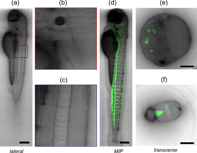
Sagittal slice of a transgenic Tg(kdrl:GFP) zebrafish (4 dpf) visualized with bright-field multi-view reconstruction (a). Details of the sample showing a portion of the head (b) and of the zebrafish notochord (c). Minimum intensity projection of the bright-field reconstruction (grey) overlapped with the maximum intensity projection of the LSFM data (green). The bright-field reconstruction shows the whole zebrafish anatomy while LSFM shows the labelled vasculature (d). Transverse section of the sample in the head (e) and tail (f), showing the bright-field reconstruction (grey) and LSFM (green). Scale bars: 100 µm.
Lastly, the environmental conditions, such as ambient lighting, should be taken into account. For example, fluorescent lights can interfere with machine vision systems, so alternative lighting sources may be needed.
Secondly, to determine the location zC of the rotational axis along the z axis, we adopted an approach typically used in OPT38. We select a single transverse section of the sample (in a certain y location), reconstruct the section assuming different zC values and calculate the contrast of each reconstruction (Fig. 3d–g), as described in Material and Methods. The reconstructed image that has the highest contrast is the closest to the ideal reconstruction, as it is the least blurred. The corresponding zC position is considered to be that of the rotation axis.
Remarkably, transmission OPT, which provides bright-field contrast, is used to correct absorption artifacts in Light Sheet Fluorescence Microscopy (LSFM)20,21 and for multimodal reconstruction of the whole specimen’s anatomy22.
Mayer, J. et al. OPTiSPIM: integrating optical projection tomography in light sheet microscopy extends specimen characterization to non-fluorescent contrasts. Opt. Lett. 39(4), 1053–1056 (2014).
On-axis lighting, also known as direct illumination, involves placing the light source in line with the camera’s optical axis. This technique provides uniform illumination on the object, which is suitable for capturing detailed features and surface conditions.
Optical Projection Tomography (OPT) is a powerful three-dimensional imaging technique used for the observation of millimeter-scaled biological samples, compatible with bright-field and fluorescence contrast. OPT is affected by spatially variant artifacts caused by the fact that light diffraction is not taken into account by the straight-light propagation models used for reconstruction. These artifacts hinder high-resolution imaging with OPT. In this work we show that, by using a multiview imaging approach, a 3D reconstruction of the bright-field contrast can be obtained without the diffraction artifacts typical of OPT, drastically reducing the amount of acquired data, compared to previously reported approaches. The method, purely based on bright-field contrast of the unstained sample, provides a comprehensive picture of the sample anatomy, as demonstrated in vivo on Arabidopsis thaliana and zebrafish embryos. Furthermore, this bright-field reconstruction can be implemented on practically any multi-view light-sheet fluorescence microscope without complex hardware modifications or calibrations, complementing the fluorescence information with tissue anatomy.
Istituto di Fotonica e Nanotecnologie, Consiglio Nazionale delle ricerche, piazza Leonardo da Vinci 32, 20133, Milan, Italy
The x location of the center of the rotation axis is found by registering two opposite views projections. The registration is performed using the Python module scikit-image (register_translation) to determine the distance Δx (Fig. 3c).
Andrews, N. et al. Visualising apoptosis in live zebrafish using fluorescence lifetime imaging with optical projection tomography to map FRET biosensor activity in space and time. J. Biophotonics 9(4), 414–424 (2016).
Walls, J. R., Coultas, L., Rossant, J. & Henkelman, R. M. Three-dimensional analysis of vascular development in the mouse embryo. PLoS ONE 3, e2853 (2008).
Bassi, A., Fieramonti, L., D’Andrea, C., Valentini, G. & Mione, M. In vivo label-free three-dimensional imaging of zebrafish vasculature with optical projection tomography. J. Biomed. Opt. 16(10), 100502 (2011).
Costa, A., Candeo, A., Fieramonti, L., Valentini, G. & Bassi, A. Calcium dynamics in root cells of Arabidopsis thaliana visualized with selective plane illumination microscopy. PLoS ONE 8, e75646 (2013).
To achieve optimal results with backlighting, you’ll need to position the light source behind the object you’re capturing. Backlighting is a technique commonly used in machine vision to detect and eliminate specular reflections on objects. It offers a range of applications in various industries, including quality control, inspection, and robotics.
BF reconstruction can be easily implemented in a multi-view light sheet microscope, complementing the high-resolution fluorescence reconstruction obtained with LSFM. In particular, we acquired images from transgenic Arabidopsis seedlings expressing the Cameleon YC3.640 under the control of AtEXP7 promoter (pEXP7:YC3.6) which directs root hair-specific expression (trichoblast cells) of the fluorescent sensor41. This acquisition shows that by combining LSFM with BF reconstruction the fluorescence can be precisely localized in the context of a single tissue sections (Fig. 4c, d) or in the entire volume (Fig. 4e). It is worth noting that the BF reconstruction is performed with a LED illumination at λ = 530 nm, close to the emission wavelength of GFP, avoiding any chromatic aberration (Fig. 4f).
Here we show that the Bright-Field (BF) contrast can be efficiently reconstructed in 3D by adopting a multi-view image processing method: we propose to fuse three-dimensional image data sets of the sample acquired at multiple angles into a single reconstruction. Each data set consists of a stack of bright-field images acquired by scanning the sample along the optical axis. The method requires the acquisition of a reduced number of angles and eliminates the diffraction artifacts, still providing isotropic resolution and 3D reconstruction of unlabeled samples. The reconstruction is not based on a back-projection algorithm, it uses a multiview fusion approach, that is frequently used in fluorescence imaging30. Here we describe how to apply this approach to reconstruct the BF contrast and we identify the optimal parameters for reconstruction as a function of the spatial and angular sampling. We present in-vivo data of Arabidopsis thaliana and zebrafish (Danio rerio) in order to demonstrate that the approach allows one to observe the whole anatomy of unstained organisms. Finally, we show that, with small modification of the hardware, BF reconstruction can be readily implemented in any multi-view Light Sheet Fluorescence Microscope (LSFM)31,32, obtaining multimodal (bright-field and fluorescence) acquisitions with the same instrument.
Bar lights are a type of machine vision lighting product that consists of multiple LEDs arranged in a linear configuration. They provide uniform illumination across the entire field of view and are commonly used for inspecting long or wide objects.
Using BF reconstruction, we managed to acquire a large volume of the biological sample in a single measurement. We tested the method in vivo with Arabidopsis thaliana and zebrafish (Danio rerio) samples. In the root of Arabidopsis seedlings, the reconstruction can be extended to a large portion of the root including the root hairs, which are long tubular-shaped outgrowths from root epidermal cells (Fig. 4 and Supplementary Fig. 3). One key feature of the technique is to provide isotropic resolution over the entire reconstructed volume. In addition, the method is label-free, since the BF reconstruction is based on trans-illumination. In living samples, the contrast is given by the attenuation of light, primarily due to scattering and absorption. Therefore, while on the one hand the staining is not required for imaging, on the other hand, since low-power light sources are used for trans-illumination, the measurements induce minimum photo-toxicity to the biological sample. These features make the technique an ideal tool for assessing the anatomy of the sample in-vivo.
With our expert insights and practical tips, you’ll learn how to choose the right lighting solution, employ effective techniques for illumination, and overcome common challenges in machine vision lighting.
Measurements of zebrafish embryos demonstrate that the whole organism can be acquired in a single experiment. Again, the technique offers the possibility to observe several organs (e.g. notochord, yolk, eye, brain) in single sections (Fig. 5a–c and Supplementary Fig. 4) and within the entire sample anatomy. The use of 4 days post fertilization (dpf) transgenic VEGFR2:GFP zebrafish embryos that express green fluorescent protein under the control of the vascular endothelial promoter VEGFR2/KDR [Tg(kdrl:GFP)]42, confirms that the combination of LSFM and BF reconstruction is a suitable tool to localize a sparse fluorescence signal in the tissue (Fig. 5d–f).
Machine vision lighting offers several benefits, including improved image contrast, increased accuracy and repeatability in inspection tasks, enhanced defect detection, and the ability to capture precise measurements. It also helps in achieving consistent results and increased productivity.
However, challenges may arise, such as dealing with reflective surfaces or overcoming ambient lighting conditions. For example, in a case study involving defect detection in automotive manufacturing, the use of specialized strobe lighting resulted in improved inspection accuracy and reduced false positives.
To achieve successful machine vision lighting, it’s important to consider factors such as light intensity, angle, and placement. These factors play a crucial role in the accuracy and reliability of machine vision systems.
So, join us as we delve into the fascinating world of machine vision lighting and unlock new possibilities for your applications.
Lastly, we must also tackle the problem of varying surface materials, as different materials can have different reflectivity properties. By understanding how different surfaces interact with light, we can develop strategies to compensate for these variations and ensure consistent and accurate machine vision inspections.
One effective method is to use polarizing filters to control the direction of light and minimize reflections. These filters can be placed in front of the camera lens or the light source to reduce glare. Another approach is to utilize diffusers to scatter the light and prevent direct reflections. Diffusers can be placed in front of the light source to achieve a more uniform and softer illumination.
In this case, the theoretical number of acquired views is \(N = \frac{2\pi n}{{NA}} \approx 48\) and the theoretical axial step is \(\Delta z = \frac{\lambda n}{{NA^{2} }} \approx 30 \;\upmu {\text{m}}\) (here λ = 530 nm). For a sample of thickness L = 300 µm the number of steps results in M ≈ 10. The results of the reconstruction performed for different values of N and M (Supplementary Fig. 1) confirm that the theoretical values are a good estimate: above N = 45 and M = 10 the increase in image contrast is negligible. The number of required views is therefore an order of magnitude smaller than the number of projections in standard OPT. Yet, the total amount of data remains practically constant because for each view a stack of images is required, but overall the acquisition time is comparable to that of standard OPT (1–5 min per sample).
To remove shadows in your machine vision system, you’ll need to implement effective shadow removal techniques. Shadows can significantly affect the accuracy and reliability of your vision system, so it’s crucial to address this issue.
Illumination machine visionsoftware
Additionally, different lighting techniques can be employed to achieve specific results. For example, using red light can be beneficial when imaging objects with high reflectivity. Understanding these critical aspects of front lighting, such as scatter and transmission, will allow you to optimize your machine vision system and attain the desired freedom in image capture.
When using vision lighting products, it is important to consider the angle at which the light is being emitted. A low angle can help generate shadows, providing depth and making the object more distinguishable. It is also crucial to ensure that the light and camera are aligned properly to minimize any unwanted reflections or glare.
Illumination machine visionapp
This approach assumes that the rotation axis is perfectly perpendicular to the optical axis of the detection objective. If this is not the case, we suggest to repeat the procedure at two or more y locations and then linearly interpolate the values of xC and zC for all the considered y values.
Candeo, A. et al. Virtual unfolding of light sheet fluorescence microscopy dataset for quantitative analysis of the mouse intestine. J. Biomed. Opt. 21(5), 056001 (2016).
Walls, J. R., Sled, J. G., Sharpe, J. & Henkelman, R. M. Correction of artefacts in optical projection tomography. Phys. Med. Biol. 50(19), 4645–4665 (2005).
LED lights offer numerous benefits in machine vision. They have higher energy efficiency and longer lifespan compared to traditional lighting sources. When it comes to machine vision, lighting plays a crucial role in achieving accurate and reliable results.
Spot lights are focused light sources that produce a concentrated beam of light. They are used to highlight specific features or areas of interest on the object being inspected, allowing for better analysis and measurement.
Consider factors such as the application, working distance, and optics to determine the most suitable vision lighting technique for your machine vision system.
Advancedillumination
How do I search by ISBN? If you choose to search by ISBN, search only by that field and make sure you type the number correctly, without any dashes.
2020111 — A growing, alternate PCB assessment approach uses cameras for automatic optical inspection of the boards. Of particular interest is to find ...
Three-dimensional optical imaging techniques are essential tools for observing the structure and understanding the function of biological samples. Among them Optical Projection Tomography (OPT), is well suited to study specimens ranging in size from hundreds of microns to a centimeter1. OPT is often considered the optical analogous of X-ray Computed Tomography (CT), performing tomographic optical imaging of three dimensional samples with transmitted and fluorescent light. OPT can be used in a number of different applications with specimens that include embryos2,3, mouse organs4,5,6 and plants7. At the same time novel OPT configurations have been presented to achieve fast acquisition8,9,10, to reconstruct the fluorescence lifetime and Förster resonance energy transfer contrast11,12, to obtain the contrast from blood flow13,14,15,16. In parallel, advanced recontruction algorithms have constantly been developed17,18,19.
Illumination systems pvt. ltd., Thane. 150 likes. leading Exporter, Manufacturer, Supplier, Trader and Importer of Lighting Products such as LED indoor...
Additionally, we will provide tips and strategies for achieving optimal illumination conditions, ensuring accurate and reliable image analysis.
By implementing these techniques, we can significantly enhance the quality and reliability of machine vision systems by minimizing the impact of glare and reflections.
by C Sanchez · 2018 · Cited by 31 — In photography, oblique light (OL) is a technique that allows to show detail by creating shadows on the surface of the object. This is one of the reasons most ...
When it comes to selecting the right lighting solution for machine vision applications, there are several factors to consider. Different types of vision lights, such as ring lights, backlighting, and coaxial lights, offer unique advantages and are suited for specific imaging tasks.
With these tools at our disposal, we can ensure a more efficient and accurate machine vision process, giving us the freedom to make informed decisions based on reliable data.
Thank you for visiting nature.com. You are using a browser version with limited support for CSS. To obtain the best experience, we recommend you use a more up to date browser (or turn off compatibility mode in Internet Explorer). In the meantime, to ensure continued support, we are displaying the site without styles and JavaScript.
Enhanced Image QualityProper lighting ensures clear and accurate imaging, allowing for more precise analysis and detection of defects or anomalies.
LED LightLED lights are energy-efficient and offer long lifetimes, making them a popular choice for machine vision systems.
After seedling germination and fluorescence inspection, the germinated fluorescent seeds were moved from the plate to the top of FEP tubes filled with gel (prepared accordingly to Candeo et al.,43 and Romano Armada et al.45, using sterilized pliers and without clamping them, so the plantlets could grow inside the filled tubes. The tubes were transferred to a tip box that was finally filled with MS/2 liquid medium without sucrose and sealed to avoid contamination. The mounting procedure and the special illumination and detection configuration of OPT-LSFM allowed the seedlings to be held from the top of the chamber in a vertical position, with the roots growing directly in the jellified medium inside the transparent tubes. To mount the tubes with the plant in the imaging chamber, we used the custom holder reported in Candeo et al.43. When plants were ready to be imaged, we plugged the pipette tip with the tube into the holder, and quickly moved it to the imaging chamber, fixing it on a rotation and translation stage for the sample positioning.
Cross, L. M., Cook, M. A., Lin, S., Chen, J. N. & Rubinstein, A. L. Rapid analysis of angiogenesis drugs in a live fluorescent zebrafish assay. Arterioscler. Thromb. Vasc. Biol. 23, 911–912 (2003).
Hyung-Taeg, C. & Cosgrove, D. J. Regulation of root hair initiation and expansin gene expression in Arabidopsis. Plant Cell 14(12), 3237–3253 (2002).
Lee, K. et al. Visualizing plant development and gene expression in three dimensions using optical projection tomography. Plant Cell 18, 2145–2156 (2006).
First, two stacks of images are acquired at opposite angles (e.g. 0° and 180°) and the two corresponding projections are created (mean intensity projection or minimum intensity projection, as shown in Fig. 3a, b). One of the two projections is flipped along the x axis and translated to overlap to the other using an image registration algorithm: in order to overlap the two images, the second projection is translated by a distance Δx (Fig. 3c). The location xC of the rotation axis is then calculated as the sum of semi-width of the image and the distance Δx/2.


 Ms.Cici
 8618319014500