
LED Invar Staff Illumination for 2m Leica bar code Invar staff - illumination bar
Relaylens
Please note that users must take care to properly mount and support the MVBT2313 lens due to its size and weight; this lens should not be solely mounted by its C-mount threads.
Each individual lens ships with a detailed test report showing the exact specifications and distortion plots for the lens, including RMS distortion, maximum distortion, magnification, maximum telecentricity, image size, and working distance. Sample reports are available in the table to the right. Raw data files are available upon request for each lens. These contain maps for distortion, absolute distortion, and telecentricity, as well as a measured data report. Graphs showing typical performance for distortion (%) vs. field height (mm) can be found on the Graphs tab above.
Thorlabs offers its own line of bi-telecentric lenses for machine vision applications. These lenses offer magnification in both image and object space that is independent of distance (within the depth of field) or the position in the field of view. This attribute is ideal for machine vision applications: when measuring dimensions, a telecentric lens will yield the same measurement regardless of changes in object distance or position. For more details on telecentric lenses and their differences from standard lenses, please see the Telecentric Tutorial tab above.
Thorlabstelecentric lens
In addition, Hyperion Optics has been working closely to innovators and photography equipment designers who develop customized anamorphic systems where use cylindrical lenses as image aspect ratio changer, such as attach-on anamorphic lenses for smart phones, anamorphic cinema projection system, and front mounted anamorphic attachment. Please check out our anamorphic lenses for more information. If you are in the stage of developing your own anamorphic lenses, don’t hesitate contacting one of our optical engineers for free consultation to receive assistant from manufacturing perspective.
Tubelens
For an image space telecentric lens, the chief rays will be parallel to the optical axis on the image's side of the lens (image space). This is accomplished by setting the aperture stop at the back focal plane of the lens, which results in an exit pupil at infinity. Since the chief rays must pass through the center of the exit pupil, the chief rays on the image side of the lens must be parallel to the optical axis. An example of an image space telecentric lens is shown in Figure 2.
For an object space telecentric lens, the chief rays will be parallel to the optical axis on the object's side of the lens (object space). This is accomplished by setting the aperture stop at the front focal plane of the lens, which results in an entrance pupil at infinity. Since chief rays are directed towards the center of the entrance pupil, the chief rays on the object side of the lens will be parallel to the optical axis. An example of an object space telecentric lens is shown in Figure 1.
Optolens
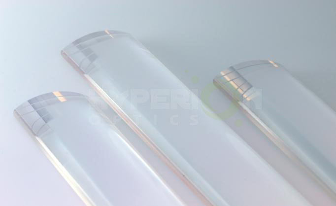
For most laser applications, Hyperion Optics’ cylindrical lenses offer always comes with competency in price; our monthly capability is 3,000 pcs. For prototyping quantity, we provide interferometry report along with the shipment upon request.
Optical lenses
At Hyperion optics, We keep utilizing optical edging technique for most demanding requirement, which is essential in cylindrical component manufacturing. We provide full inspection data along with shipment including Zygo interferometry report and centering testing results.
Liquidlensedmund optics
Cylindrical lenses are used to focus, expand or condense light into a single dimension. Cylindrical lenses are widely used in laser scanners, optical information processing and computing, dye lasers or anamorphic lenses. Hyperion Optics has decade of cylindrical lenses manufacturing experience, ranging from ordinary plano-convex, plano-concave to cemented achromatic cylindrical lenses. For most laser applications, Hyperion Optics’ cylindrical lenses offer always comes with competency in price; our monthly capability is 3,000 pcs. For prototyping quantity, we provide interferometry report along with the shipment upon request. In addition, Hyperion Optics has been working closely to innovators and photography equipment designers who develop customized anamorphic systems where use cylindrical lenses as image aspect ratio changer, such as attach-on anamorphic lenses for smart phones, anamorphic cinema projection system, and front mounted anamorphic attachment. Please check out our anamorphic lenses for more information. If you are in the stage of developing your own anamorphic lenses, don’t hesitate contacting one of our optical engineers for free consultation to receive assistant from manufacturing perspective. At Hyperion optics, We keep utilizing optical edging technique for most demanding requirement, which is essential in cylindrical component manufacturing. We provide full inspection data along with shipment including Zygo interferometry report and centering testing results. Cylindrical Lenses COMMERCIAL GRADE FACTORY STANDARD PRECISION GRADE Size Tolerance Length/Width(mm) +0/-0.30 +0/-0.25 +0/-0.25 Diameter (mm) +0/-0.15 +0/-0.10 ±0.025 Wedge (along axis) 5 mrad 3 mrad 1 mrad Focal Length Tolerance (%) ±2% ±2% ±1% Cosmetic(MIL-C-13830A) 80-50 60-40 10-5 Irregularity (Lambda @ 632.8nm) 1 L 1/2 L 1/10 L Centration (Arc min) <5' <3' <1' Coating (T% avg) 99% 99.5% 99.5% Materials Optical Glasses Depends On Design
Telecentricillumination
Telecentric lenses are designed to have a constant magnification regardless of the object's distance or location in the field of view. This attribute is ideal for many machine vision measurement applications, as measurements of an object's dimensions will be independent of where it is located.
Opto Engineering
For a double telecentric, or bi-telecentric, lens, the front and back focal planes are made to overlap so that the aperture stop is located where both the entrance and exit pupils are at infinity. In a bi-telecentric lens, neither the image or object location will affect the magnification. Thorlabs' telecentric lenses are all bi-telecentric designs. Figure 3 shows an example ray trace through a bi-telecentric lens and illustrates how the chief rays pass through the system.
Types of Telecentric LensesIn order to achieve a telecentric lens design, all of the chief rays (rays from an off-axis point that pass through the center of the aperture stop) have to be parallel to the optical axis in either image space or object space, or both.
These lenses are designed for 2/3" format sensors, such as those used in a variety of our scientific CMOS cameras. Sensors smaller than 2/3" can also be used but with reduced field of view. The lens housing features external C-mount (1.000"-32) threading on the image side of the lens, which is also compatible with many of our cameras. By using an SM1A10 thread adapter, the C-mount can be mated to internal SM1 (1.035"-40) threads for compatibility with our lens tubes or other SM1-threaded mounts. CS-Mount cameras are compatible with these lenses when using a CML05 CS- to C-Mount adapter.
Conventional LensesIn conventional lenses, the entrance and exit pupils are not located at infinity, so the chief rays will not be parallel to the optical axis. In this case, the magnification of the object depends on its distance from the lens and its position in the field of view. Figure 4 above shows an example ray trace through a conventional camera lens; notice how the chief rays are angled with respect to the optical axis in both image and object space. Note that both Figures 3 and 4 feature the same lens design; only the aperture stop location was varied to shift the bi-telecentric system to a non-telecentric one.
These graphs show the theoretically calculated distortion modeling results from Zemax. Each individual lens ships with a detailed test report showing the exact specifications and distortion plots for the lens, including RMS distortion, maximum distortion, magnification, maximum telecentricity, image size, and working distance. A sample report for each lens can be viewed on the Overview tab.
Cylindrical Lenses COMMERCIAL GRADE FACTORY STANDARD PRECISION GRADE Size Tolerance Length/Width(mm) +0/-0.30 +0/-0.25 +0/-0.25 Diameter (mm) +0/-0.15 +0/-0.10 ±0.025 Wedge (along axis) 5 mrad 3 mrad 1 mrad Focal Length Tolerance (%) ±2% ±2% ±1% Cosmetic(MIL-C-13830A) 80-50 60-40 10-5 Irregularity (Lambda @ 632.8nm) 1 L 1/2 L 1/10 L Centration (Arc min) <5' <3' <1' Coating (T% avg) 99% 99.5% 99.5% Materials Optical Glasses Depends On Design
Cylindrical lenses are used to focus, expand or condense light into a single dimension. Cylindrical lenses are widely used in laser scanners, optical information processing and computing, dye lasers or anamorphic lenses. Hyperion Optics has decade of cylindrical lenses manufacturing experience, ranging from ordinary plano-convex, plano-concave to cemented achromatic cylindrical lenses.
Example ImagesFigures 5 and 6 show photographs taken with a bi-telecentric lens and a standard camera lens, respectively. With the telecentric imaging system, the height of the two screws appears to be the same, even though the object planes are separated by approximately 45 mm along the optical axis. With the conventional imaging system, the two screws appear to be different heights, which could result in inaccurate dimensional measurements. A machine vision system using a bi-telecentric lens can offer advantages for dimensional metrology. For example, these lenses can be integrated into our Multi-Sensor Video Measurement Machines.


 Ms.Cici
 8618319014500