
Dark-field Microscopy: Principle and Uses - definition of dark field microscope
7pin wiring diagram
When looking at a 5 pin relay wiring diagram for a horn, it is important to understand the various components involved in the system. This includes the relay itself, which acts as a switch to control the flow of electricity to the horn. Additionally, the diagram will show how the horn is connected to the relay, as well as any other necessary wiring. By fully understanding this diagram, you can ensure that your horn functions properly and efficiently. Let's delve deeper into the details of each component and their roles in the wiring diagram.
The most common type of relay used in automotive applications is the 5-pin relay. This type of relay has five pins: two for the coil, which creates the magnetic field that closes the relay contacts, and three for the contacts themselves. The contacts are typically labeled as common (C), normally open (NO), and normally closed (NC).
5 pin wiring diagram12v
A key benefit of using a 5-pin relay wiring diagram for horns is the ability to integrate a horn switch into the vehicle's existing electrical system seamlessly. This setup ensures that the horn operates smoothly and avoids any potential voltage drop or power loss that could occur with a direct connection. In addition, the use of a relay provides added protection to the horn and the vehicle's electrical system, prolonging their lifespan.
A relay is an electrical switch that allows a low-powered circuit to control a high-powered circuit. In the case of a horn system, a relay is often used to switch the high current needed to power the horn.
5 pin wiring diagrampdf
For convenient connection to the drivers listed below and on the LED Drivers tab, the LED ring light has a connection cable with an M8 connector; see the Pin Diagram tab for the M8 connector pin information. This LED ring light also features an EEPROM chip which stores information about the LED (e.g., current limit, forward voltage). When controlled by a Thorlabs UPLED, DC40, or DC2200 LED driver, this data can be used to implement smart safety features.
5 pin wiring diagramautomotive
The diagram to the right shows the male connector of the LEDRW40 Ring Light. It is a standard M8 x 1 sensor circular connector. Pins 1 and 2 are the connection to the LED. Pin 3 and 4 are used for the internal EEPROM. If using an LED driver that was not purchased from Thorlabs, be careful that the appropriate connections are made to Pin 1 and Pin 2 and that you do not attempt to drive the LED through the EEPROM pins.
White Light LEDsThis illuminator is a daylight white LED ring featuring a broad spectrum that spans several hundred nanometers; see the table to the right for a typical output spectrum. It has a correlated color temperature 5500 K, which indicates that the color appearance is similar to a black body radiator at the same temperature. In general, warm white LEDs offer a spectrum similar to a tungsten source, while cold white LEDs have a stronger blue component to the spectrum; daylight white LEDs provide a more even illumination spectrum over the visible range than warm white or cold white LEDs. To discuss LED ring lights with other correlated color temperatures or nominal wavelengths, please contact Tech Support.
5 pin wiring diagram4pin
This tab includes all LEDs sold by Thorlabs. Click on More [+] to view all available wavelengths for each type of LED pictured below.
Did you know that relays are electromagnetic switches used to control circuits in various electrical applications? They come in different configurations, including 4-pin and 5-pin relays. A popular use of relays is in automotive electrical systems to control devices such as horns. One common wiring diagram for horns involves the use of a 5-pin relay, which provides a reliable way to activate the horn in vehicles.
5 pin wiring diagramchevy
If you encounter issues with the horn wiring using a relay, you can check for loose connections, faulty components, or a blown fuse as potential causes of the problem.
To fully support the max optical power of the LED you intend to drive, ensure that the max voltage and max current of the driver are equal to or greater than those of the LED.
Thorlabs also offers a range of unmounted, mounted, collimated, and fiber-coupled LEDs that are designed for a variety of applications, including microscopy, illumination, and measurements. For questions on choosing an appropriate LED and to discuss mounting requirements, please contact Tech Support.
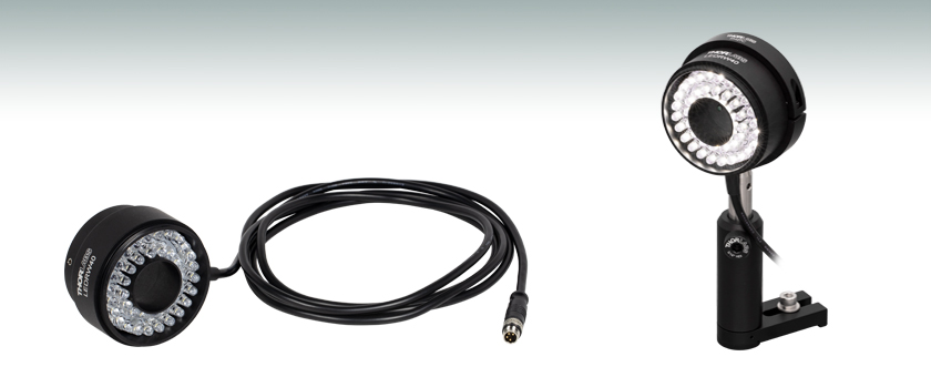
Constructed from anodized aluminum, this LED ring light housing features four 4-40 tapped holes that are compatible with our Ø6 mm ER cage rods, allowing for integration with 30 mm cage systems. The housing also features three setscrews on the sides for interfacing with various camera lenses and high-magnification zoom lens systems (as seen in the photo in the bottom right), which can be secured using a 5/64" (2.0 mm) hex key or balldriver. An M60 x 1.0 external thread at the head of the ring light gives the option of attaching various elements such as custom filters or diffusers.
4pin wiring diagram
The fuse is an important safety feature in the wiring of a horn using a relay as it protects the electrical system from any potential damage caused by a short circuit or overload.
5 pintrailerwiring diagram
To test the wiring of the horn with the relay, you can use a multimeter to check for continuity and proper voltage levels at different points in the circuit.
In conclusion, wiring a 5 pin relay for a horn is a simple and efficient way to control the horn in a vehicle. By following a clear diagram and understanding the function of each pin, users can easily install the relay and ensure reliable operation of the horn. Remember to connect the relay to the appropriate power source, ground, horn switch, and horn itself to ensure proper functionality. With the right tools and knowledge, anyone can successfully wire a 5 pin relay for a horn.
It is important to ensure that the relay is installed correctly and that the wiring is secure to prevent any potential issues with the horn system. Following the wiring diagram carefully will help ensure that the horn functions properly and reliably when needed.
The horn should be connected to the relay by connecting one terminal of the horn to the common terminal of the relay, and the other terminal of the horn to the normally open terminal of the relay.
Thorlabs' LED Ring Light Source consists of 40 individual broadband, daylight white LEDs in a ring-shaped array with a Ø0.99" (Ø25.1 mm) clear aperture. By angling the LEDs, this ring light illuminates areas from 50 mm to 300 mm along the emission axis that can then be viewed through the clear aperture, making it ideal for machine vision applications.
According to automotive experts, proper installation of a 5-pin relay wiring diagram for horns can significantly improve the overall performance and reliability of the horn system in vehicles. By following the wiring diagram correctly and using high-quality components, vehicle owners can ensure that their horns operate effectively whenever needed. Whether for safety reasons or signaling purposes, a properly installed relay wiring diagram can make a big difference in the functionality of a vehicle's horn system.
According to a recent survey, approximately 85% of vehicles are equipped with horns that utilize relays for proper functionality. This highlights the importance of understanding how to correctly wire a horn with a 5-pin relay for optimal performance.
In the past, horns were directly connected to the vehicle's power source, often causing issues with reliability and performance. The introduction of 5-pin relay wiring diagrams revolutionized how horns were activated in vehicles. By using a relay, the horn can be powered directly from the battery without drawing power through the horn switch, resulting in a more efficient and dependable horn system.
Driver OptionsThorlabs offers four drivers compatible with this LED ring light: LEDD1B, DC40, UPLED, and DC2200. See the LED Drivers tab for compatibility information and a list of specifications. The UPLED, DC40, and DC2200 drivers are capable of reading the current limit from the EEPROM chip of the connected LED ring light and automatically adjusting the maximum current setting to protect the LEDs. The DC40 LED driver can provide drive currents with up to a 5 kHz modulation when supplied with an external modulation signal. While the DC2200 driver is capable of modulating frequencies up to 250 kHz, the LED ring light must not be modulated at or above 9 kHz.


 Ms.Cici
 8618319014500