
Kohärenz und Wahrscheinlichkeit - koharenz
The shoulder is located at the base of the objective threading and marks the beginning of the exposed objective body when it is fully threaded into a nosepiece or other objective mount.
The camera sensor dimensions can be obtained from the manufacturer, while the system magnification is the multiplicative product of the objective magnification and the camera tube magnification (see Example 1). If needed, the objective magnification can be adjusted as shown in Example 3.
This microscope objective serves only as an example. The features noted above with an asterisk may not be present on all objectives; they may be added, relocated, or removed from objectives based on the part's needs and intended application space.
Krones ebimachine
The most common, a standard #1.5 cover glass, is designed to be 0.17 mm thick. Due to variance in the manufacturing process the actual thickness may be different. The correction collar present on select objectives is used to compensate for cover glasses of different thickness by adjusting the relative position of internal optical elements. Note that many objectives do not have a variable cover glass correction, in which case the objectives have no correction collar. For example, an objective could be designed for use with only a #1.5 cover glass. This collar may also be located near the bottom of the objective, instead of the top as shown in the diagram.
Submit your request to receive IRIS “Good news”: latest innovations, updates and hot topics related to smart glass inspection!
This scaling gives adjusted LIDT values of 0.08 J/cm2 for the reflective filter and 14 J/cm2 for the absorptive filter. In this case, the absorptive filter is the best choice in order to avoid optical damage.
Now compare the maximum energy density to that which is specified as the LIDT for the optic. If the optic was tested at a wavelength other than your operating wavelength, the damage threshold must be scaled appropriately [3]. A good rule of thumb is that the damage threshold has an inverse square root relationship with wavelength such that as you move to shorter wavelengths, the damage threshold decreases (i.e., a LIDT of 1 J/cm2 at 1064 nm scales to 0.7 J/cm2 at 532 nm):
202486 — The Timeline of Cameras · Pinhole Camera (5th century BC) · Daguerreotype Camera (1839) · Kodak Camera (1888) · Compact Cameras (1900s) · SLR ...
Note that Leica, Mitutoyo, Nikon, and Thorlabs use the same tube lens focal length; if combining elements from any of these manufacturers, no conversion is needed. Once the effective objective magnification is calculated, the magnification of the system can be calculated as before.
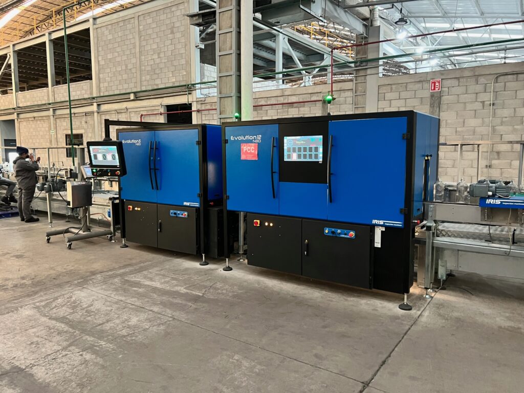
NEO intelligence is based on an innovative defect approach that relates to defect identification, as well as the creation of statistics by defect type. Local trend analyses are produced on the machine, with information presented in a user-friendly format.
LIDT in linear power density vs. pulse length and spot size. For long pulses to CW, linear power density becomes a constant with spot size. This graph was obtained from [1].
Kronesmachine
202019 — A beam of partially polarized light can be considered to be a mixture of polarized and unpolarized light. Suppose we send such a beam ...
When an optic is damaged by a continuous wave (CW) laser, it is usually due to the melting of the surface as a result of absorbing the laser's energy or damage to the optical coating (antireflection) [1]. Pulsed lasers with pulse lengths longer than 1 µs can be treated as CW lasers for LIDT discussions.
These objectives are designed to be used without a cover glass and do not feature a correction collar. Imaging through a cover glass may cause spherical aberrations in an image, depending on the numerical aperture of the objective. See the Objective Tutorial tab for more on how a cover glass may impact performance. For biological applications where imaging through cover glasses is required, consider our apochromatic objectives for life science.
Objectives are commonly divided by their class. An objective's class creates a shorthand for users to know how the objective is corrected for imaging aberrations. There are two types of aberration corrections that are specified by objective class: field curvature and chromatic aberration.
Pulses shorter than 10-9 s cannot be compared to our specified LIDT values with much reliability. In this ultra-short-pulse regime various mechanics, such as multiphoton-avalanche ionization, take over as the predominate damage mechanism [2]. In contrast, pulses between 10-7 s and 10-4 s may cause damage to an optic either because of dielectric breakdown or thermal effects. This means that both CW and pulsed damage thresholds must be compared to the laser beam to determine whether the optic is suitable for your application.
If an objective is used for water dipping, water immersion, or oil immersion, a second colored ring may be placed beneath the magnification identifier. If the objective is designed to be used with water, this ring will be white. If the objective is designed to be used with oil, this ring will be black. Dry objectives lack this identifier ring entirely. See the table to the right for a complete list of immersion identifiers.
While this rule of thumb provides a general trend, it is not a quantitative analysis of LIDT vs wavelength. In CW applications, for instance, damage scales more strongly with absorption in the coating and substrate, which does not necessarily scale well with wavelength. While the above procedure provides a good rule of thumb for LIDT values, please contact Tech Support if your wavelength is different from the specified LIDT wavelength. If your power density is less than the adjusted LIDT of the optic, then the optic should work for your application.
Krones glassbottlefiller
Additionally, the objective label area may include the objective's specified wavelength range, specialty features or design properties, and more. The exact location and size of each and any of these elements can vary.
As previously stated, pulsed lasers typically induce a different type of damage to the optic than CW lasers. Pulsed lasers often do not heat the optic enough to damage it; instead, pulsed lasers produce strong electric fields capable of inducing dielectric breakdown in the material. Unfortunately, it can be very difficult to compare the LIDT specification of an optic to your laser. There are multiple regimes in which a pulsed laser can damage an optic and this is based on the laser's pulse length. The highlighted columns in the table below outline the relevant pulse lengths for our specified LIDT values.
References[1] Eugene Hecht, "Optics," 4th Ed., Addison-Wesley (2002)[2] S.G. Lipson, H. Lipson, and D.S. Tannhauser, "Optical Physics," 3rd Ed., Cambridge University Press (1995)[3] C.M. Sparrow, "On Spectroscopic Resolving Power," Astrophys. J. 44, 76-87 (1916)
Thorlabs offers Mitutoyo Plan Apochromat Near-Infrared (NIR) Objectives with 5X, 10X, 20X, or 50X magnification. They feature a flat field of focus and chromatic correction in the visible range with extended transmission to 1800 nm. The long working distance provides a wide space making them ideal for machine vision applications or laser focusing. Each objective is engraved with its class, magnification, numerical aperture, a zero (noting that it is to be used to image a sample without a cover glass), and the tube lens focal length for which the specified magnification is valid. For an explanation of the defining properties of these objectives, please see the Objective Tutorial tab. If the case shipped with each of these objectives is lost or broken, Thorlabs offers an objective case (item #s OC2M26 and OC24) that can be used as a replacement.
Example 4: Sample AreaThe dimensions of the camera sensor in Thorlabs' previous-generation 1501M-USB Scientific Camera are 8.98 mm × 6.71 mm. If this camera is used with the Nikon objective and trinoculars from Example 1, which have a system magnification of 15X, then the image area is:
The adjusted LIDT value of 350 W/cm x (1319 nm / 1550 nm) = 298 W/cm is significantly higher than the calculated maximum linear power density of the laser system, so it would be safe to use this doublet lens for this application.
The energy density of your beam should be calculated in terms of J/cm2. The graph to the right shows why expressing the LIDT as an energy density provides the best metric for short pulse sources. In this regime, the LIDT given as an energy density can be applied to any beam diameter; one does not need to compute an adjusted LIDT to adjust for changes in spot size. This calculation assumes a uniform beam intensity profile. You must now adjust this energy density to account for hotspots or other nonuniform intensity profiles and roughly calculate a maximum energy density. For reference a Gaussian beam typically has a maximum energy density that is twice that of the 1/e2 beam.
Objectives that feature a built-in iris diaphragm are ideal for darkfield microscopy. The iris diaphragm is designed to be partially closed during darkfield microscopy in order to preserve the darkness of the background. This is absolutely necessary for high numerical aperture (above NA = 1.2) oil immersion objectives when using an oil immersion darkfield condenser. For ordinary brightfield observations, the iris diaphragm should be left fully open.
The working distance, often abbreviated WD, is the distance between the front element of the objective and the top of the specimen (in the case of objectives that are intended to be used without a cover glass) or top of the cover glass. The cover glass thickness specification engraved on the objective designates whether a cover glass should be used.
Reduced dependence on human intervention was a key goal for this strategic development, which brings the smart factory concept ever closer.
Example 2: Trinocular MagnificationWhen imaging a sample through trinoculars, the image is magnified by the objective and the eyepieces in the trinoculars. If using a 20X Nikon objective and Nikon trinoculars with 10X eyepieces, then the image at the eyepieces has 20X × 10X = 200X magnification. Note that the image at the eyepieces does not pass through the camera tube, as shown by the drawing to the right.
According to the test, the damage threshold of the mirror was 2.00 J/cm2 (532 nm, 10 ns pulse, 10 Hz, Ø0.803 mm). Please keep in mind that these tests are performed on clean optics, as dirt and contamination can significantly lower the damage threshold of a component. While the test results are only representative of one coating run, Thorlabs specifies damage threshold values that account for coating variances.
Objectives with very small working distances may have a retraction stopper incorporated into the tip. This is a spring-loaded section which compresses to limit the force of impact in the event of an unintended collision with the sample.
Thorlabs offers long working distance M Plan objectives for ultraviolet (UV), visible, or near-infrared (NIR) wavelength ranges. These objectives are designed for use with a tube lens focal length of 200 mm and are ideal for machine vision applications or applications that require a significant distance between the objective lens and the object. See the Specs tab for details on each of the objectives available here.
Five objective classes are shown in the table to the right; only three common objective classes are defined under the International Organization for Standards ISO 19012-2: Microscopes -- Designation of Microscope Objectives -- Chromatic Correction. Due to the need for better performance, we have added two additional classes that are not defined in the ISO classes.
The effective magnification of the Olympus objective is 22.2X and the trinoculars have 10X eyepieces, so the image at the eyepieces has 22.2X × 10X = 222X magnification.
Pulsed Nanosecond Laser Example: Scaling for Different WavelengthsSuppose that a pulsed laser system emits 10 ns pulses at 2.5 Hz, each with 100 mJ of energy at 1064 nm in a 16 mm diameter beam (1/e2) that must be attenuated with a neutral density filter. For a Gaussian output, these specifications result in a maximum energy density of 0.1 J/cm2. The damage threshold of an NDUV10A Ø25 mm, OD 1.0, reflective neutral density filter is 0.05 J/cm2 for 10 ns pulses at 355 nm, while the damage threshold of the similar NE10A absorptive filter is 10 J/cm2 for 10 ns pulses at 532 nm. As described on the previous tab, the LIDT value of an optic scales with the square root of the wavelength in the nanosecond pulse regime:
In the image below, two Airy disks are shown separated by the Abbe resolution limit. Compared to the Rayleigh limit, the decrease in intensity at the origin is much harder to discern. The horizontal line cut to the right shows that the intensity decreases by only ≈2%.
Thorlabs offers a High-Resolution Plan Apochromatic Improved Visible (APO VIS+) Microscope Objective for 400 to 1100 nm that provides axial color correction over a wide field of view with no vignetting over the entire field. Compared to common apochromatic microscope objectives, which are typically axial color corrected from the 436 nm (g-line) to 656 nm (C-line), our PLAN APO VIS+ objective has an extended corrected wavelength range from 436 nm (g-line) to 850 nm. The objective is designed for use with a tube lens focal length of 200 mm and has optical elements that are AR-coated for improved transmission between 400 nm and 1100 nm. For more details on these objectives, please click the info icon () below. Our 50X objective has a high numerical aperture (NA) of 0.75, making it ideal for applications requiring high-resolution such as laser focusing; brightfield, darkfield, and fluorescence microscopy; and two-photon imaging. Each objective is shipped in an objective case comprised of an OC2M26 lid and an OC24 canister.
KRONES Checkmat manual PDF
Each objective is engraved with its class, magnification, numerical aperture, wavelength range, a zero (noting that it is to be used to image a sample without a cover glass), and optical field number. For an explanation of the defining properties of these objectives, please see the Objective Tutorial tab.
The labeling area for an objective usually falls in the middle of the objective body. The labeling found here is dictated by ISO 8578: Microscopes -- Marking of Objectives and Eyepieces, but not all manufacturers adhere strictly to this standard. Generally, one can expect to find the following information in this area:
Following Equation 1 and the table to the right, we calculate the effective magnification of an Olympus objective in a Nikon microscope:
Model : GLASS-GX480 An optional frosted glass diffuser used for Microscope Ring Light (GX-480).
As described above, the maximum energy density of a Gaussian beam is about twice the average energy density. So, the maximum energy density of this beam is ~0.7 J/cm2.
Kronesinspection machine
Questo significa che la risoluzione angolare di un sistema limitato alla diffrazione è data dalla stessa formula. Ma in una macchina digitale, magari reflex ...
Sempre con riferimento alla diffrazione significa raccogliere , per esempio con una lente , la figura di diffrazione nella zona del fuoco della lente. Si ...
Threading allows an objective to be mounted to a nosepiece or turret. Objectives can have a number of different thread pitches; Thorlabs offers a selection of microscope thread adapters to facilitate mounting objectives in different systems.
In order to facilitate fast identification, nearly all microscope objectives have a colored ring that circumscribes the body. A breakdown of what magnification each color signifies is given in the table below.
For a thin double convex lens, refraction acts to focus all parallel rays to a point referred to as the principal focal point. The distance from the lens to ...
EBImachine
We also offer a 15X APO VIS+ objective, TL15X-2P, that is optimized for multiphoton imaging and features a lockable correction collar that allows adjustment for spherical aberrations introduced by imaging through aqueous solutions or cover glasses up to 2.8 mm thick.
The calculation above assumes a uniform beam intensity profile. You must now consider hotspots in the beam or other non-uniform intensity profiles and roughly calculate a maximum power density. For reference, a Gaussian beam typically has a maximum power density that is twice that of the uniform beam (see lower right).
All of the objectives found on this page have a parfocal length of 95 mm (see the Specs tab for complete specifications). To use them alongside other manufacturer standards, such as Nikon objectives with a 60 mm parfocal length, we offer parfocal length extenders. For instance, the PLE351 Extender can be used to increase the parfocal length of a Nikon objective from 60 mm to 95 mm.
This adjustment factor results in LIDT values of 0.45 J/cm2 for the BB1-E01 broadband mirror and 1.6 J/cm2 for the Nd:YAG laser line mirror, which are to be compared with the 0.7 J/cm2 maximum energy density of the beam. While the broadband mirror would likely be damaged by the laser, the more specialized laser line mirror is appropriate for use with this system.
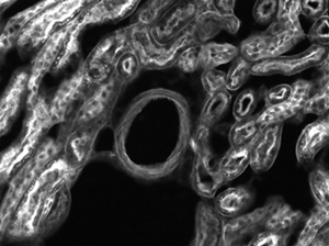
The images of a mouse kidney below were all acquired using the same objective and the same camera. However, the camera tubes used were different. Read from left to right, they demonstrate that decreasing the camera tube magnification enlarges the field of view at the expense of the size of the details in the image.
An AC127-030-C achromatic doublet lens has a specified CW LIDT of 350 W/cm, as tested at 1550 nm. CW damage threshold values typically scale directly with the wavelength of the laser source, so this yields an adjusted LIDT value:
The Rayleigh criterion states that two overlapping Airy disk profiles are resolved when the first intensity minimum of one profile coincides with the intensity maximum of the other profile [1]. It can be shown that the first intensity minimum occurs at a radius of 1.22λf/D from the central maximum, where λ is the wavelength of the light, f is the focal length of the objective, and D is the entrance pupil diameter. Thus, in terms of the numerical aperture (NA = 0.5*D/f), the Rayleigh resolution is:
Use only 3 watts to replace standard 15W halogens. 12Vmonster brings you a low voltage PAR16 edison screw medium base that works with AC DC 12 volt lighting ...
Please note that we have a buffer built in between the specified damage thresholds online and the tests which we have done, which accommodates variation between batches. Upon request, we can provide individual test information and a testing certificate. The damage analysis will be carried out on a similar optic (customer's optic will not be damaged). Testing may result in additional costs or lead times. Contact Tech Support for more information.
If this relatively long-pulse laser emits a Gaussian 12.7 mm diameter beam (1/e2) at 980 nm, then the resulting output has a linear power density of 5.9 W/cm and an energy density of 1.2 x 10⁻⁴ J/cm2 per pulse. This can be compared to the LIDT values for a WPQ10E-980 polymer zero-order quarter-wave plate, which are 5 W/cm for CW radiation at 810 nm and 5 J/cm2 for a 10 ns pulse at 810 nm. As before, the CW LIDT of the optic scales linearly with the laser wavelength, resulting in an adjusted CW value of 6 W/cm at 980 nm. On the other hand, the pulsed LIDT scales with the square root of the laser wavelength and the square root of the pulse duration, resulting in an adjusted value of 55 J/cm2 for a 1 µs pulse at 980 nm. The pulsed LIDT of the optic is significantly greater than the energy density of the laser pulse, so individual pulses will not damage the wave plate. However, the large average linear power density of the laser system may cause thermal damage to the optic, much like a high-power CW beam.
When imaging a sample with a camera, the dimensions of the sample area are determined by the dimensions of the camera sensor and the system magnification, as shown by Equation 2.
The following is a general overview of how laser induced damage thresholds are measured and how the values may be utilized in determining the appropriateness of an optic for a given application. When choosing optics, it is important to understand the Laser Induced Damage Threshold (LIDT) of the optics being used. The LIDT for an optic greatly depends on the type of laser you are using. Continuous wave (CW) lasers typically cause damage from thermal effects (absorption either in the coating or in the substrate). Pulsed lasers, on the other hand, often strip electrons from the lattice structure of an optic before causing thermal damage. Note that the guideline presented here assumes room temperature operation and optics in new condition (i.e., within scratch-dig spec, surface free of contamination, etc.). Because dust or other particles on the surface of an optic can cause damage at lower thresholds, we recommend keeping surfaces clean and free of debris. For more information on cleaning optics, please see our Optics Cleaning tutorial.
When pulse lengths are between 1 ns and 1 µs, laser-induced damage can occur either because of absorption or a dielectric breakdown (therefore, a user must check both CW and pulsed LIDT). Absorption is either due to an intrinsic property of the optic or due to surface irregularities; thus LIDT values are only valid for optics meeting or exceeding the surface quality specifications given by a manufacturer. While many optics can handle high power CW lasers, cemented (e.g., achromatic doublets) or highly absorptive (e.g., ND filters) optics tend to have lower CW damage thresholds. These lower thresholds are due to absorption or scattering in the cement or metal coating.
Field curvature (or Petzval curvature) describes the case where an objective's plane of focus is a curved spherical surface. This aberration makes widefield imaging or laser scanning difficult, as the corners of an image will fall out of focus when focusing on the center. If an objective's class begins with "Plan", it will be corrected to have a flat plane of focus.
To adapt the examples shown here to your own microscope, please use our Magnification and FOV Calculator, which is available for download by clicking on the red button above. Note the calculator is an Excel spreadsheet that uses macros. In order to use the calculator, macros must be enabled. To enable macros, click the "Enable Content" button in the yellow message bar upon opening the file.
The Abbe theory describes image formation as a double process of diffraction [2]. Within this framework, if two features separated by a distance d are to be resolved, at a minimum both the zeroth and first orders of diffraction must be able to pass through the objective's aperture. Since the first order of diffraction appears at the angle: sin(θ1) = λ/d, the minimum object separation, or equivalently the resolution of the objective, is given by d = λ/n*sin(α), where α is the angular semi-aperture of the objective and a factor of n has been inserted to account for the refractive index of the imaging medium. This result overestimates the actual limit by a factor of 2 because both first orders of diffraction are assumed to be accepted by the objective, when in fact only one of the first orders must pass through along with the zeroth order. Dividing the above result by a factor of 2 and using the definition of the numerical aperture (NA = n*sin(α)) gives the famous Abbe resolution limit:
Images can also exhibit chromatic aberrations, where colors originating from one point are not focused to a single point. To strike a balance between an objective's performance and the complexity of its design, some objectives are corrected for these aberrations at a finite number of target wavelengths.
The resolution of an objective refers to its ability to distinguish closely-spaced features of an object. This is often theoretically quantified by considering an object that consists of two point sources and asking at what minimum separation can these two point sources be resolved. When a point source is imaged, rather than appearing as a singular bright point, it will appear as a broadened intensity profile due to the effects of diffraction. This profile, known as an Airy disk, consists of an intense central peak with surrounding rings of much lesser intensity. The image produced by two point sources in proximity to one another will therefore consist of two overlapping Airy disk profiles, and the resolution of the objective is therefore determined by the minimum spacing at which the two profiles can be uniquely identified. There is no fundamental criterion for establishing what exactly it means for the two profiles to be resolved and, as such, there are a few criteria that are observed in practice. In microscopic imaging applications, the two most commonly used criteria are the Rayleigh and Abbe criteria. A third criterion, more common in astronomical applications, is the Sparrow criterion.
However, the maximum power density of a Gaussian beam is about twice the maximum power density of a uniform beam, as shown in the graph to the right. Therefore, a more accurate determination of the maximum linear power density of the system is 1 W/cm.
Each objective housing is engraved with key specifications including the magnification, the numerical aperture, and an infinity symbol noting that it is infinity corrected; see the image to the right. The housings have external W26 x 0.706 threads.
Objectives can be divided by what medium they are designed to image through. Dry objectives are used in air; whereas dipping and immersion objectives are designed to operate with a fluid between the objective and the front element of the sample.
List of camera types · 360 camera (VR camera) · 3D camcorder · Action camera · Animation camera · Autofocus camera · Backup camera · Banquet camera · Body camera ...
The magnification of a system is the multiplicative product of the magnification of each optical element in the system. Optical elements that produce magnification include objectives, camera tubes, and trinocular eyepieces, as shown in the drawing to the right. It is important to note that the magnification quoted in these products' specifications is usually only valid when all optical elements are made by the same manufacturer. If this is not the case, then the magnification of the system can still be calculated, but an effective objective magnification should be calculated first, as described below.
LIDT in energy density vs. pulse length and spot size. For short pulses, energy density becomes a constant with spot size. This graph was obtained from [1].
An important parameter in many imaging applications is the resolution of the objective. This tutorial describes the different conventions used to define an objective's resolution. Thorlabs provides the theoretical Rayleigh resolution for all of the imaging objectives offered on our site; the other conventions are presented for informational purposes.
Pulsed lasers with high pulse repetition frequencies (PRF) may behave similarly to CW beams. Unfortunately, this is highly dependent on factors such as absorption and thermal diffusivity, so there is no reliable method for determining when a high PRF laser will damage an optic due to thermal effects. For beams with a high PRF both the average and peak powers must be compared to the equivalent CW power. Additionally, for highly transparent materials, there is little to no drop in the LIDT with increasing PRF.
Objectives following ISO 8578: Microscopes -- Marking of Objectives and Eyepieces will be labeled with an identifier ring to tell the user what immersion fluid the objective is designed to be used with; a list of ring colors can be found in the table to the right.
An idealized image of two Airy disks separated by a distance equal to the Rayleigh resolution is shown in the figure to the left below; the illumination source has been assumed to be incoherent. A corresponding horizontal line cut across the intensity maxima is plotted to the right. The vertical dashed lines in the intensity profile show that the maximum of each individual Airy disk overlaps with the neighboring minimum. Between the two maxima, there is a local minimum which appears in the image as a gray region between the two white peaks.
This objective is engraved with its class, magnification, numerical aperture, a zero (noting that it is to be used to image a sample without a cover glass), and optical field number. For an explanation of the defining properties of this objective, please see the Objective Tutorial tab.
An innovative defect approach that relates to defect identification, as well as the creation of statistics by defect type. Local trend analyses are produced on the machine, with information presented in a user-friendly format.
Thorlabs can provide these objectives with custom AR coatings on request by contacting Tech Support; options include broadband NUV (325 nm - 500 nm), dual band (266 and 532 nm), and laser line (248 nm, 266 nm, 355 nm, or 532 nm). We also offer additional MicroSpot objectives for laser-focusing applications in the UV as well as visible and near-IR wavelengths.
Now compare the maximum power density to that which is specified as the LIDT for the optic. If the optic was tested at a wavelength other than your operating wavelength, the damage threshold must be scaled appropriately. A good rule of thumb is that the damage threshold has a linear relationship with wavelength such that as you move to shorter wavelengths, the damage threshold decreases (i.e., a LIDT of 10 W/cm at 1310 nm scales to 5 W/cm at 655 nm):
For point source separations corresponding to the Rayleigh and Abbe resolution criteria, the combined intensity profile has a local minimum located at the origin between the two maxima. In a sense, this feature is what allows the two point sources to be resolved. That is to say, if the sources' separation is further decreased beyond the Abbe resolution limit, the two individual maxima will merge into one central maximum and resolving the two individual contributions will no longer be possible. The Sparrow criterion posits that the resolution limit is reached when the crossover from a central minimum to a central maximum occurs.
At the Sparrow resolution limit, the center of the combined intensity profile is flat, which implies that the derivative with respect to position is zero at the origin. However, this first derivative at the origin is always zero, given that it is either a local minimum or maximum of the combined intensity profile (strictly speaking, this is only the case if the sources have equal intensities). Consider then, that because the Sparrow resolution limit occurs when the origin's intensity changes from a local minimum to a maximum, that the second derivative must be changing sign from positive to negative. The Sparrow criterion is thus a condition that is imposed upon the second derivative, namely that the resolution limit occurs when the second derivative is zero [3]. Applying this condition to the combined intensity profile of two Airy disks leads to the Sparrow resolution:
Use this formula to calculate the Adjusted LIDT for an optic based on your pulse length. If your maximum energy density is less than this adjusted LIDT maximum energy density, then the optic should be suitable for your application. Keep in mind that this calculation is only used for pulses between 10-9 s and 10-7 s. For pulses between 10-7 s and 10-4 s, the CW LIDT must also be checked before deeming the optic appropriate for your application.
Magnification is not a fundamental value: it is a derived value, calculated by assuming a specific tube lens focal length. Each microscope manufacturer has adopted a different focal length for their tube lens, as shown by the table to the right. Hence, when combining optical elements from different manufacturers, it is necessary to calculate an effective magnification for the objective, which is then used to calculate the magnification of the system.
The pulse length must now be compensated for. The longer the pulse duration, the more energy the optic can handle. For pulse widths between 1 - 100 ns, an approximation is as follows:
CW Laser ExampleSuppose that a CW laser system at 1319 nm produces a 0.5 W Gaussian beam that has a 1/e2 diameter of 10 mm. A naive calculation of the average linear power density of this beam would yield a value of 0.5 W/cm, given by the total power divided by the beam diameter:
Pulsed Nanosecond Laser Example: Scaling for Different Pulse DurationsSuppose that a pulsed Nd:YAG laser system is frequency tripled to produce a 10 Hz output, consisting of 2 ns output pulses at 355 nm, each with 1 J of energy, in a Gaussian beam with a 1.9 cm beam diameter (1/e2). The average energy density of each pulse is found by dividing the pulse energy by the beam area:
Thorlabs expresses LIDT for CW lasers as a linear power density measured in W/cm. In this regime, the LIDT given as a linear power density can be applied to any beam diameter; one does not need to compute an adjusted LIDT to adjust for changes in spot size, as demonstrated by the graph to the right. Average linear power density can be calculated using the equation below.
Dipping objectives are designed to correct for the aberrations introduced by the specimen being submerged in an immersion fluid. The tip of the objective is either dipped or entirely submerged into the fluid.
As the magnification increases, the resolution improves, but the field of view also decreases. The dependence of the field of view on magnification is shown in the schematic to the right.
Immersion objectives are similar to water-dipping objectives; however, in this case the sample is under a cover glass. A drop of fluid is then added to the top of the cover glass, and the tip of the objective is brought into contact with the fluid. Often, immersion objectives feature a correction collar to adjust for cover glasses with different thicknesses. Immersion fluids include water, oil (such as MOIL-30), and glycerol.
Using an immersion fluid with a high refractive index allows objectives to achieve numerical apertures greater than 1.0. However, if an immersion objective is used without the fluid present, the image quality will be very low. Objectives following ISO 8578: Microscopes -- Marking of Objectives and Eyepieces will be labeled with an identifier ring to tell the user what immersion fluid the objective is designed to be used with; a list of ring colors can be found in the table above.
Pulsed Microsecond Laser ExampleConsider a laser system that produces 1 µs pulses, each containing 150 µJ of energy at a repetition rate of 50 kHz, resulting in a relatively high duty cycle of 5%. This system falls somewhere between the regimes of CW and pulsed laser induced damage, and could potentially damage an optic by mechanisms associated with either regime. As a result, both CW and pulsed LIDT values must be compared to the properties of the laser system to ensure safe operation.
Here, the Design Magnification is the magnification printed on the objective, fTube Lens in Microscope is the focal length of the tube lens in the microscope you are using, and fDesign Tube Lens of Objective is the tube lens focal length that the objective manufacturer used to calculate the Design Magnification. These focal lengths are given by the table to the right.
The energy density of the beam can be compared to the LIDT values of 1 J/cm2 and 3.5 J/cm2 for a BB1-E01 broadband dielectric mirror and an NB1-K08 Nd:YAG laser line mirror, respectively. Both of these LIDT values, while measured at 355 nm, were determined with a 10 ns pulsed laser at 10 Hz. Therefore, an adjustment must be applied for the shorter pulse duration of the system under consideration. As described on the previous tab, LIDT values in the nanosecond pulse regime scale with the square root of the laser pulse duration:
In order to illustrate the process of determining whether a given laser system will damage an optic, a number of example calculations of laser induced damage threshold are given below. For assistance with performing similar calculations, we provide a spreadsheet calculator that can be downloaded by clicking the button to the right. To use the calculator, enter the specified LIDT value of the optic under consideration and the relevant parameters of your laser system in the green boxes. The spreadsheet will then calculate a linear power density for CW and pulsed systems, as well as an energy density value for pulsed systems. These values are used to calculate adjusted, scaled LIDT values for the optics based on accepted scaling laws. This calculator assumes a Gaussian beam profile, so a correction factor must be introduced for other beam shapes (uniform, etc.). The LIDT scaling laws are determined from empirical relationships; their accuracy is not guaranteed. Remember that absorption by optics or coatings can significantly reduce LIDT in some spectral regions. These LIDT values are not valid for ultrashort pulses less than one nanosecond in duration.
Beam diameter is also important to know when comparing damage thresholds. While the LIDT, when expressed in units of J/cm², scales independently of spot size; large beam sizes are more likely to illuminate a larger number of defects which can lead to greater variances in the LIDT [4]. For data presented here, a <1 mm beam size was used to measure the LIDT. For beams sizes greater than 5 mm, the LIDT (J/cm2) will not scale independently of beam diameter due to the larger size beam exposing more defects.
Thorlabs offers Mitutoyo Plan Apochromat Objectives with 7.5X, 10X, 20X, 50X, or 100X magnification. They feature a flat field of focus and chromatic correction in the visible range. The long working distance provides a wide space between the lens surface and the object making them ideal for machine vision applications. Each objective is engraved with its class, magnification, numerical aperture, a zero (noting that it is to be used to image a sample without a cover glass), and the tube lens focal length for which the specified magnification is valid. For an explanation of the defining properties of these objectives, please see the Objective Tutorial tab. If the case shipped with each of these objectives is lost or broken, Thorlabs offers an objective case (item #s OC2M26 and OC24) that can be used as a replacement.
A cover glass, or coverslip, is a small, thin sheet of glass that can be placed on a wet sample to create a flat surface to image across.
Objectives following ISO 8578: Microscopes -- Marking of Objectives and Eyepieces will be labeled with an identifier ring to tell the user what immersion fluid the objective is designed to be used with; a list of ring colors can be found in the table to the right.
Thorlabs provides the theoretical Rayleigh resolution for all of the imaging objectives offered on our site in their individual product presentations.
Thorlabs' LIDT testing is done in compliance with ISO/DIS 11254 and ISO 21254 specifications.First, a low-power/energy beam is directed to the optic under test. The optic is exposed in 10 locations to this laser beam for 30 seconds (CW) or for a number of pulses (pulse repetition frequency specified). After exposure, the optic is examined by a microscope (~100X magnification) for any visible damage. The number of locations that are damaged at a particular power/energy level is recorded. Next, the power/energy is either increased or decreased and the optic is exposed at 10 new locations. This process is repeated until damage is observed. The damage threshold is then assigned to be the highest power/energy that the optic can withstand without causing damage. A histogram such as that below represents the testing of one BB1-E02 mirror.
[1] R. M. Wood, Optics and Laser Tech. 29, 517 (1998).[2] Roger M. Wood, Laser-Induced Damage of Optical Materials (Institute of Physics Publishing, Philadelphia, PA, 2003).[3] C. W. Carr et al., Phys. Rev. Lett. 91, 127402 (2003).[4] N. Bloembergen, Appl. Opt. 12, 661 (1973).
Also referred to as the parfocal distance, this is the length from the shoulder to the top of the specimen (in the case of objectives that are intended to be used without a cover glass) or the top of the cover glass. When working with multiple objectives in a turret, it is helpful if all of the parfocal distances are identical, so little refocusing will be required when switching between objectives. Thorlabs offers parfocal length extenders for instances in which the parfocal length needs to be increased.
Example 1: Camera MagnificationWhen imaging a sample with a camera, the image is magnified by the objective and the camera tube. If using a 20X Nikon objective and a 0.75X Nikon camera tube, then the image at the camera has 20X × 0.75X = 15X magnification.
20231114 — A backlight, which is partially composed of two layers of polarizing material with a liquid crystal solution between them, is used to illuminate ...
Please note that we have a buffer built in between the specified damage thresholds online and the tests which we have done, which accommodates variation between batches. Upon request, we can provide individual test information and a testing certificate. Contact Tech Support for more information.
The image to the left below shows two Airy disks separated by the Sparrow resolution limit. As described above, the intensity is constant in the region between the two peaks and there is no intensity dip at the origin. In the line cut to the right, the constant intensity near the origin is confirmed.
Example 3: Trinocular Magnification (Different Manufacturers)When imaging a sample through trinoculars, the image is magnified by the objective and the eyepieces in the trinoculars. This example will use a 20X Olympus objective and Nikon trinoculars with 10X eyepieces.
CES is the State Hub of Environmental Information System (ENVIS) Programme. CES is compiling and Distributing newsletters to stakeholders on environmental ...
Thorlabs MicroSpot objectives provide long working distances while keeping axial focal shift low. Their optical design is chromatically optimized in the UV wavelength range. Diffraction-limited performance is guaranteed over the entire clear aperture. These objectives are ideal for laser cutting, surgical laser focusing, and spectrometry applications. They can also be used for scanning and micro-imaging applications like brightfield imaging under narrowband, UV laser illumination. Each objective is shipped in an objective case comprised of an OC2M26 lid and an OC24 canister.


 Ms.Cici
 8618319014500